When venturing into the world of 3D printing, a fundamental aspect of controlling your printer is familiarity with G-codes and M-codes. G-codes (geometric codes) and M-codes (miscellaneous codes) are sets of instructions that command the movements, actions, and operations of your 3D printer. In the context of Klipper firmware, mastering these codes becomes particularly valuable for customizing and optimizing your printing experience.
The Power of G-Codes: Navigating the 3D Space
G-codes are the backbone of 3D printing, dictating how the printer’s motors should move to produce a desired object layer by layer. Whether it’s a rapid movement to a new position (G0), a controlled extrusion of filament (G1), or homing all axes (G28), G-codes are the language through which you communicate with your 3D printer. Understanding and utilizing G-codes allows you to control the printer’s movements with precision, enabling the creation of intricate and accurate prints.
Example:
G1 X10 Y20 Z30 F3000
In this example, the printer is instructed to move to the coordinates X=10, Y=20, Z=30 at a feed rate of 3000 mm/min.
Navigating System Operations with M-Codes
Complementing G-codes, M-codes handle miscellaneous functions such as temperature control, bed leveling, and emergency stops. These codes govern crucial aspects of the printing process, ensuring that the printer operates within specified temperature ranges, executes proper homing procedures, and handles emergencies responsibly.
Example:
M104 S200
This M-code sets the extruder temperature to 200 degrees Celsius, ensuring the filament is at the optimal temperature for extrusion.
Why Knowing G-Codes and M-Codes Matters
Understanding G-codes and M-codes empowers 3D printing enthusiasts to optimize their printing workflows. Knowing how to home the printer, control temperatures, and manage extrusion precisely allows for the fine-tuning of prints and troubleshooting of potential issues.
Moreover, delving into these codes opens up possibilities for customization. Whether you’re adjusting the speed of movements, implementing auto bed leveling (G29), or defining specific extrusion rates (G92), G-codes and M-codes provide the flexibility needed to tailor your 3D printing experience to your exact specifications.
As you navigate the world of 3D printing with Klipper firmware, this cheat sheet serves as a handy reference, condensing essential G-codes and M-codes into a single, accessible resource. Mastery of these codes transforms the seemingly complex task of 3D printing into a more manageable and customizable endeavor, allowing you to unleash the full potential of your 3D printer.
3D Printing G-Code Cheat Sheet
Here is a quick one pager we’ve prepared that we keep close to out 3D printing workstation, very helpful for when reading g-code for troubleshooting, or when you’re writing your own macros.
**Movement Commands**
G0 / G1
Rapid / Linear Move Example: `G1 X10 Y20 Z30 F3000`
G28
Home all axes Example: `G28`
G92
Set position Example: `G92 E0` (reset extruder position to 0)
**Temperature Control**
M104
Set extruder temperature Example: `M104 S200`
M140
Set bed temperature Example: `M140 S60`
M109
Wait for extruder temperature Example: `M109 S200`
M190
Wait for bed temperature Example: `M190 S60`
**Extrusion Control**
M82 / M83
Set extruder to absolute (M82) or relative (M83) mode Example: `M82`
G92 E
Set extruder position (used with absolute mode) Example: `G92 E10`
G1 E
Extrude filament Example: `G1 E10 F100`
**Positioning Modes**
G90
Set to absolute positioning mode Example: `G90`
G91
Set to relative positioning mode Example: `G91`
**Bed Leveling and Mesh**
G29
Auto bed leveling Example: `G29`
G80
Cancel mesh bed leveling Example: `G80`
**Fan Control**
M106
Turn on fan Example: `M106 S255`
M107
Turn off fan Example: `M107`
**System Commands**
M112
Emergency stop Example: `M112`
M503
Print settings (configured in firmware) Example: `M503`
So you’ve forgotten your Password on your ECU. We’ve all been there…
This article isn’t about why your ECU has a password on it, nor is it an invitation to discuss why or who might have put the password on it. We are open to discussions about how to better secure passwords on ECUs and other techniques on how to recover passwords off ECUs though.
This article is about the nuts and bolts around how to recover the password off a locked ECU.
Today’s subject is the LinkECU G4 series of ECUs, a very popular ECU for good reason, it ticks a lot of boxes for a lot of people.
Link G4 Password Removal Process
So to begin the password recovery you will need:
A PC with PC Link G4 installed on it.
Some form of spreadsheet software (Google sheets or Excel)
“Notepad ++” software installed
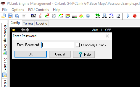
So because this article is strictly for entertainment and education purposes, and never to be used for any actual password recovery in the wild, we’ll begin by opening PCLink G4, opening a new base map, lock it with a password, and “Save As” new file name.
Now we’ve got our password protected calibration file to try and recover the password from.
Next up we’ll close PCLink and open our new calibration file in Notepad++ and what we’re greeted with is a wall of numbers, not quite human readable but not encrypted by any means.
Looking a Link G4 calibration file in Notepadd++
So you can search through these 40 thousand numbers to see if your password is in there, and at first glance it’s not there; only numbers. So where is the password? Oh it’s in there, you just need to read like a computer. The password is stored in ASCII. ASCII (American Standard Code for Information Interchange) is a character encoding system that represents text and symbols in digital devices using a 7-bit or 8-bit code.
So now we’re talking bits and bytes, but what you might have noticed in the notepad file while you were looking for your password, none of the values between the commas were below 0 or above 255. Every value between the commas is an 8-bit value, expressed in the notepad document in decimal format. (0-255) We’ll get into the differences in Binary, Decimal and Hexadecimal in another CANbus article, for now though let’s proceed and get someone else do the heavy lifting in the brain department.
We need to dump all this information into a spreadsheet and use the formula =CHAR() to find our password.
If we just copied all the data out of the LinkMemData line into our spreadsheet, each comma would make a new column, which at 14,119 would violate the maximum amount of columns you can have in a spreadsheet, so we need to transpose the data into rows before we send it into our spreadsheet.
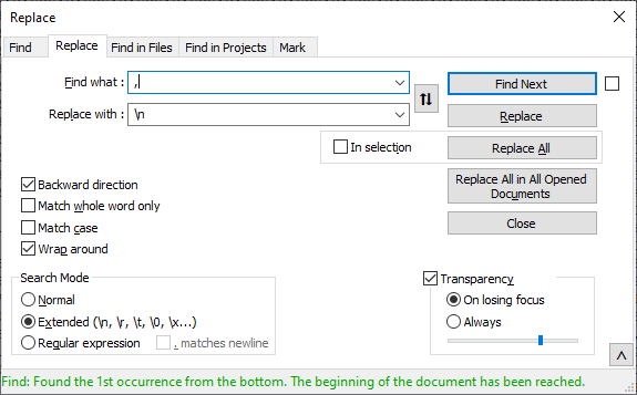
To do this we’ll use the find and replace feature in notepad++ and replace every comma with a line break.
make sure that extended button is pressed
Finding commas, replacing it with \n, making sure the extended button is enabled, the hit replace all. This takes a second, then you’ll see you’ve got one line per number, now select all of it, and paste it into your spreadsheet.
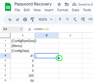
Now with all your data pasted into your spreadsheet, you should have it all in one column, and one value per line. In a cell that’s adjacent to a number value enter the formula
=CHAR(A4)
Decimal to ASCII Conversion
Where A4 is the cell which has the number value in it. Then Press Enter. Your spreadsheets software might suggest an auto fill which is to do the same formula all the way through which is perfect. If it doesn’t suggest it, you can double click on the little dot in the bottom right of the cell where your formula is.
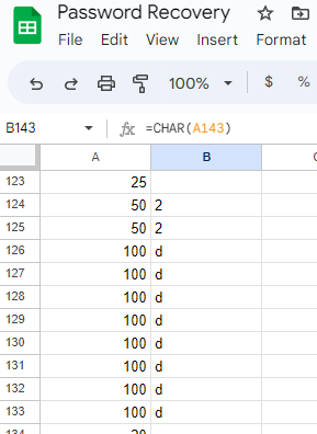
Extend the formula down to the bottom
This will continue your formula down all the way to the bottom of the table.
So now you might be seeing some letters in here with some human readable text!
Numbers converted from Decimal to ASCII
I’ll give you the tip, my password wasn’t 22dddddddd. So let’s keep scrolling. Scrolling, scrolling, scrolling… scrolling forever, until your mouse wheel has given up and you’ve had to swap hands lest you do yourself an injury, continue scrolling, making sure to read every letter, it might be your long lost password, keep scrolling down, hoping you haven’t missed it…
But then, you’ll see it, a string of letters, albeit vertically aligned, it’s unmistakable, and one of the best words you’ll see all day.
A word so unmistakably amazing, it evokes sweet and lustful emotions in most, promotes salivation and a desire to consume.
You’ll find this word held in the highest regard by people all over the world, its beauty and brilliance crosses all cultures and borders.
The word found on the 9784th line of this spreadsheet means a lot to me, means a lot to you.
Delicious dairy treat, a yellow kind of meat.
So here is your password! Congratulations!
Make sure you use this information for good and not evil.
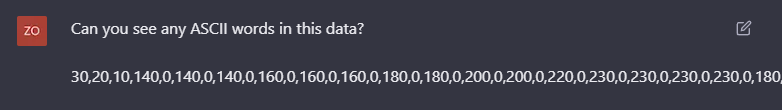
Also if you can’t be bothered with the Notepad++ or Spreadsheet, you can just ask chatGPT if it can see any ASCII words in the file you point it at.
Yep, we’re all doomed.
So this technique works for the Link G4 and other ECUs of a similar vintage.
Later model standalone ECUs make it a little more difficult to get the passwords out, they will encrypt the calibration files and hash the passwords which significantly increases the difficulty of recovering the passwords out of them. We’ve got other techniques for recovering those passwords which we look forward to sharing with you later.
If you liked this article, consider subscribing to our mailing list to get more juicy, nerdy, racecar articles delivered straight to your inbox.
Time Attack Tas (TaT) is an event we very much look forward to every year, competing in every event since its inception.
This year was another great event organised by the Hobart Sporting Car Club at Baskerville. We’re very grateful for their continued dedication to the sport and this event.
Peter competed in his R33 Skyline GTST and took 2nd place in Club Class. Peter negotiated his usual struggle for traction and drove his way to a new PB of 59.1 seconds.
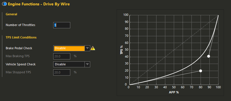
Peter often drives with a heavy foot which is the cause of the majority of his traction issues. We were able to assist slightly in the part throttle area of driving by changing the mapping of the drive by wire throttle.
Another reason we love drive by wire.
You can see here in the NSP software, the vertical axis is the actual percentage of throttle opening vs the horizontal axis which is the accelerator pedal position. The dashed line represents a linear relationship, which is close to where we started, and the solid line is where we finished for the day, giving the driver much more part throttle “resolution”. This significantly improved part throttle drivability and made it easier to get out of corners cleanly, contributing to the new PB.
NSP makes this very easy to map with the spline handles you can use to drag the curve around. This feature isn’t unique to Haltech though, with most ECU manufactures offering this feature too.
Our beloved EVO piloting tuner, Ash, was also competing and was able to secure 3rd place with a 59.6 lap time, unfortunately unable to drive his vehicle home though, that story for another time…
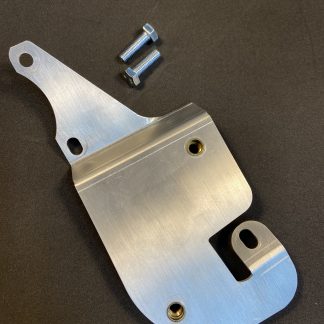
We’ve been so fortunate to be invited into a rather special build and offer our part design, prototype and manufacturing services to aid in the completion of “LEGIT” R34 Skyline.
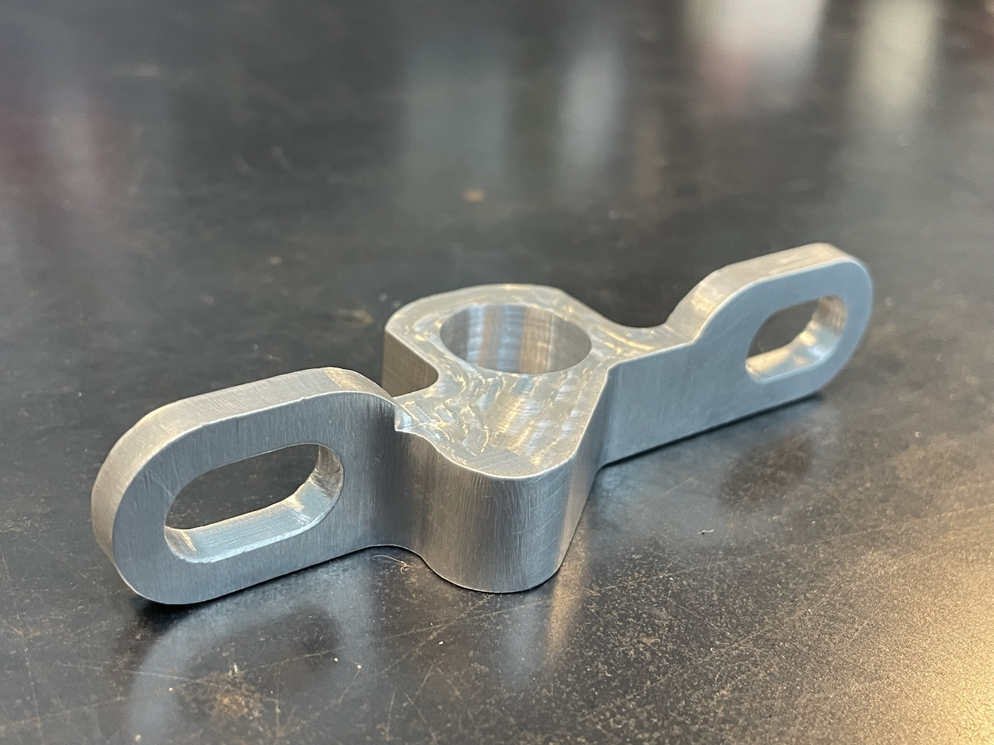
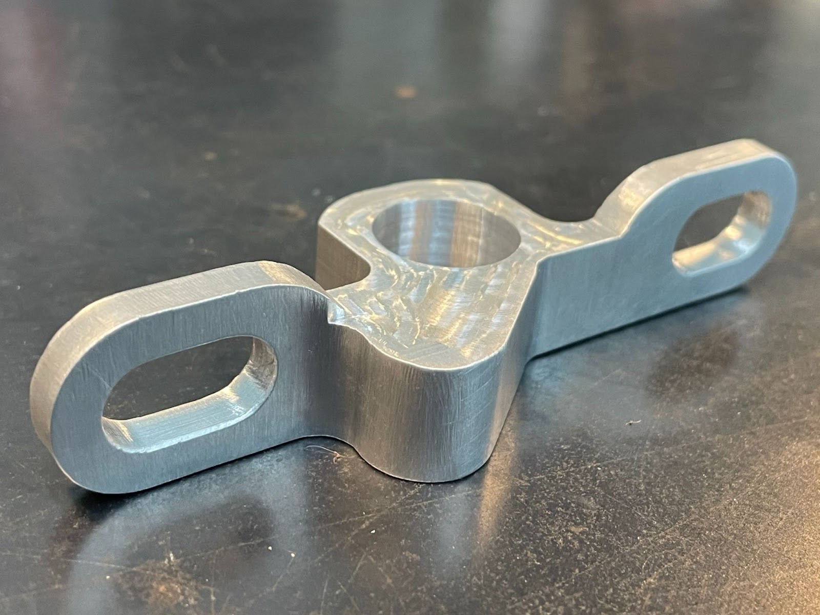
VR38 Crank Angle Sensor Bracket, CNC Machined from 6061 Billet.
Above is the Crank angle sensor mount for the VR38VETT. As the engine has a dry sump fitted, the factory crank angle sensor mounting is removed and a new one must be fabricated. We took careful measurements of the bell housing area where the mount was to go, then modeled in Fusion 360 a part to suit, 3D Printed a prototype and test fitted. It wasn’t perfect the first time so we adjusted the model and prototyped 2 more parts before cutting it out of a 6061 Aluminum billet.
The other part we were commissioned to make was the alternator bracket. Because of the exhaust system that accommodates the single turbo conversion, a new LS style alternator was to be fitted. Test fitting the alternator was painful as space was tight in the engine bay when the engine and exhaust manifolds were fitted. So with the engine out of the car, we first 3D scanned the engine bay, then we 3D scanned the engine with the turbo manifolds fitted. Then we took those 3D scans and opened them together in Fusion 360. We then downloaded the CAD asset for a LS alternator and offered it up to the engine while the engine was in the vehicle virtually. With the alternator in place in CAD, we could then design an alternator bracket to suit.
Imported scan data. Engine in Pink, Body in Green, Alternator in Grey and new Bracket in Blue. Doesn’t look too pretty but that’s over 1gb of scan data!
We 3D printed the prototype bracket and it was a near perfect fit, just a millimeter here and there to adjust and it was ready to make out of aluminum.
The finished product! Fits like a glove.
The finished product looked great and will serve its purpose very well. We learned a lot about what our little mill is capable of and it’s only driven our desire to make more parts!
We’re working on a customers car today, installing a Haltech IC7 to work with a Link G4X XtremeX, at first glance it’s not a particularly challenging installation, but as usual; we found a challenge for ourselves that introduced a twist.
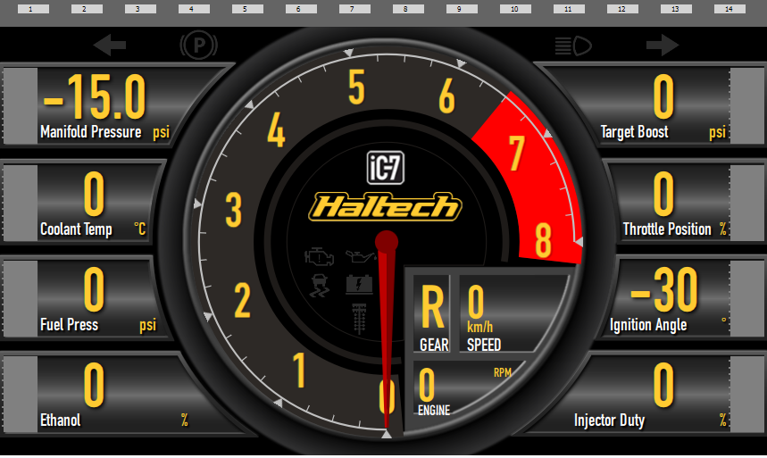
Upon setting up the IC7, we set it up in Link G4 Mode and set the Link ECU to output the generic CAN stream to suit, now we’re in business. Upon first powerup, all was going well, all the sensors were coming through as expected but on some screens, there was a glaring omission, the warning lights in the center console were not working. This is a pretty disappointing detail that’s missing from the IC7 Display when using it with a Link ECU, not being able to light up the CEL, Oil warning, Battery warning, TC or LC lights. Plus they’re just there mocking you, not working, the whole time, on most of the screens.
Default Haltech IC7 Screen, you can see the unilluminatable warning lights in the center.
So the challenge now is obvious, get these warning lights on the Haltech IC7 working with a Link ECU…
So with the Haltech IC7 there didn’t seem to be any CAN messages that would toggle the warning lights, I trawled through all the LinkECU and Haltech documentation to no avail, I found the CAN messages that ‘should’ turn the lights on, but they didn’t do anything no matter how I sent them over.
So I defaulted the IC7 back to Haltech V2, and using my ECU Master USB to CAN and the Light client software, sent the CAN messages that should toggle the lights and voilà, they worked as expected.
So let’s ask the LinkECU to send down the Haltech Dash protocol…. Unfortunately this isn’t an option. Time to dive into the Link’s Custom CAN stream settings.
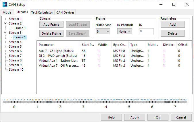
So if we look at the Haltech CANbus documentation, we can see that all the lights we want to use are on the one address (0x3E4 or 996) so with 5 lights to choose from, we opted to use 4 of them. Check Engine light, Oil Pressure Warning, Battery Warning and Launch Control.
Why Launch control? Well, this car is a GU Nissan Patrol with 4WD and it’s nice to know when you’re in 4WD. One option would be to get a pilot light and mount that in the cluster somewhere, but to save the visual appeal of the Mako Motorsport Custer we decided that it needed to go into the IC7 but how…. Launch control isn’t a feature we needed a light for on the dash as its status will be reflected on the CANkey pad, so we wired up the standard 4WD light wire (Behind the dash, white connector, White\Violet wire) that goes to the dash and routed it into one of the spare Digital inputs, this digital input is configured to a GP Input and as the 4WD switch, switches from floating to ground, we enabled the pullup resistor.
Then we set the 4WD status to go into the CAN User Stream on the right bit to light up the LC light on the IC7.
Screen shot of the LinkECU CAN Stream frame to toggle the warning lights on the IC7
So with this CAN Stream Setup, we can enjoy the fruits of our labour!
Warning lights: operational.
So you’re probably noticing the custom logo in the center and the 4WD light has replaced the standard LC Christmas tree. Stay tuned for how we complete that in another article, but for now! Back to CANbus settings.
So we’ve got the warning lights operational, but now none of the sensors work! Well the thing to do now is to write Link User CAN stream that will suit what the Dash is expecting to hear from a Haltech ECU, this seems like an arduous task but if we look at the above screen, it’s actually only 11 different sensors that actually only go across 4 CAN messages. I found it helpful to set the dash up to display what the customer wanted to see and then find those messages in the documentation, because the dash isn’t capable of any logging, there is no need to send messages for sensor data we’re not going to look at on the display.
To give you a bit of a head start if you decide to endeavor on a project similar to this, find here a zip with the Link Streams saved for your reference. I’m going to call it mission accomplished on this project, I learned a couple of new tricks and the customer got something pretty cool.
In this article we will discuss CANbus Hacking, or CAN Hacking. Specifically, the first step into CAN hacking, to actually get on the CANbus; to plug into the network and start to see the data.
You probably already have your reason as to ‘why’ you want to get on the CANbus and hopefully this article can help you achieve your goals.
This article won’t get too bogged down with what CANbus is and why it works the way it does, there is enough information on wikipedia already for those of you who are interested in that, it’s not very relevant to our goals here. All you really need to know is, CANbus is a 2 wire communications bus, you can add more devices to the CANbus by connecting CAN high and CAN low wires to the CANbus. Pretty much anywhere on the CANbus is fine too, there are many best practices to follow to design a reliable CANbus network, but that’s not what we’re doing here today. We’re just getting on it and reading the messages.
So to start with, we’re going to find some equipment that will allow us to connect to a CANbus and view the data being broadcasted on the network, and also transmit some messages too. Once we’ve selected our equipment, we’ll set it up appropriately for connecting it temporarily to a CANbus. Then when the equipment is ready, we will inspect our target vehicle, identify the correct wire\connectors to interface with and hopefully from there we can find our CANbus information and messages.
Equipment Selection
Equipment you will need:
Laptop computer.
USB to CAN Device
20ga Wires
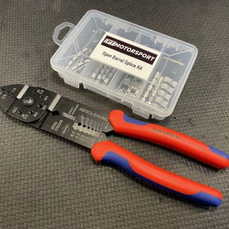
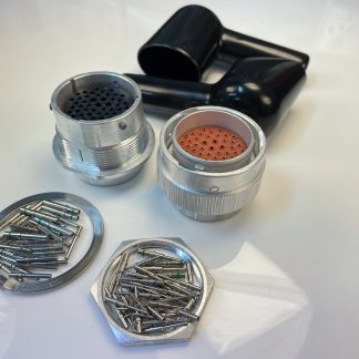
4 Position DTM Deutsch Connectors and spare pins.
So, you’ve probably still got a few questions, let’s dig in a bit deeper about the equipment we can use.
Laptop Computer.
The hardware requirements aren’t going to be too high on this one, any computers that’s running windows 10 that performs well will be appropriate. I’m using windows for this demo but if you want to use Mac or Linux, they’re both workable options too.
You can use a desktop computer if you choose, it just limits your location slightly.
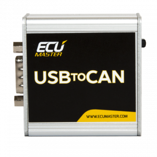
USB to CAN device.
There are a few USB to CAN devices out there on the market, all ranging in price and functionality. I’ve had a great amount of success with the Canable Pro from the canable.io project, but they’re no longer available unfortunately, but there are still chinese copies available from the usual suspects, they’re marketed as a “Cando Pro USB to Can Module” Untested by myself, buyer beware.
There are also a good variety of Arduino and Raspberry Pi projects you can do to make modules that will send and receive CAN data. I’ve done a few projects now and they in themselves are a bit of fun but require a significant amount of effort to get operational, so if your goal is to learn a little more about CANbus, this could be a good option.
If your goal is to get on the CANbus and see CAN messages in order to get some components, that should work together, to actually work together. Then you’ll want to skip straight to the “ECU Master USB to CAN”. This device isn’t a budget option but when you consider the software that is included and the ease with which it will be set up, it’s a no brainer.
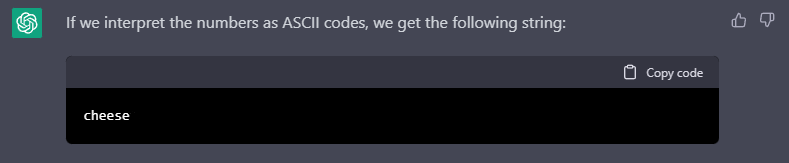
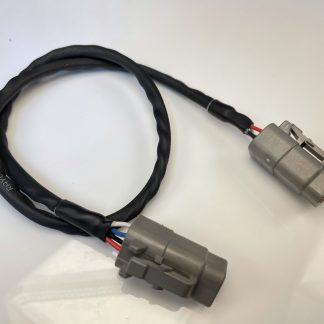
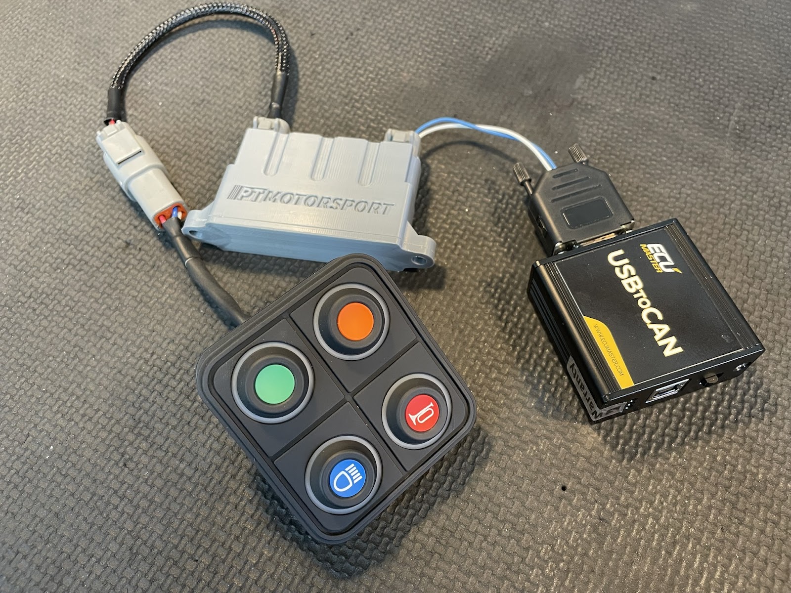
A PT Motorsport CAN hub connects a 4 Button CAN Keypad to a ECU Master USB to CAN
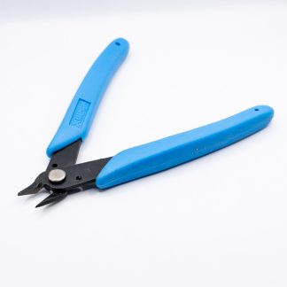
20ga Wires.
We’re using the Spec 44 (M81044/12-20) wiring for our projects, it’s what we’ve got in stock but it also has the advantage of being quite stiff and the sheathing is robust. So when you’re pinning and repinning and pushing the wire into connectors, it’ll comply with your request. Colour choices are also free but at PT Motorsport, we use White for CAN high and Blue for CAN Low, unless we’re integrating with an existing harness, then we’ll match those colours.
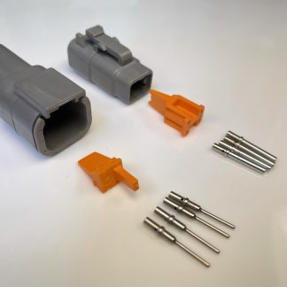
DTM Connectors and Spare Pins.
At PT Motorsport, we follow the Automotive aftermarket trend of using 4 Position Deutsch Connectors for our CAN projects. With the pinout being as follows.
Pin1. +12v (red)
Pin2. Battery Ground (Black)
Pin3. CAN Hi
Pin4. CAN Lo
Be aware, while this is the standard many popular aftermarket ECU manufacturers follow, it is not the same for all of them. Please bear that in mind and check your pinouts if you’re integrating into an existing harness or device.
Spare pins are for connecting to the hookup leads in order to probe your connectors and get a good connection. DTM Pins are a nice small size, they can be connected into many different style connectors without damaging the connector. You can also back probe connectors with them too and because the pins are nicely rounded on the tips, you lower the risk of damaging a connector or a wires sheathing in the process.
Now that we have our components and equipment selected, we can continue on our quest for CANbus information.
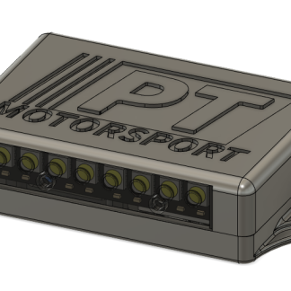
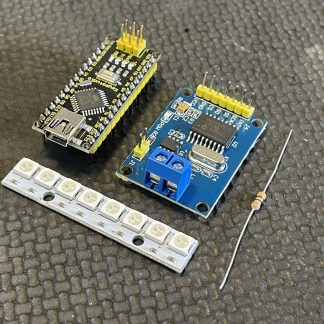
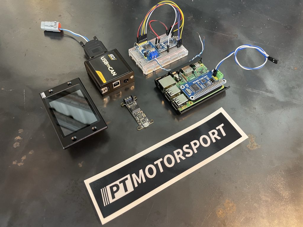
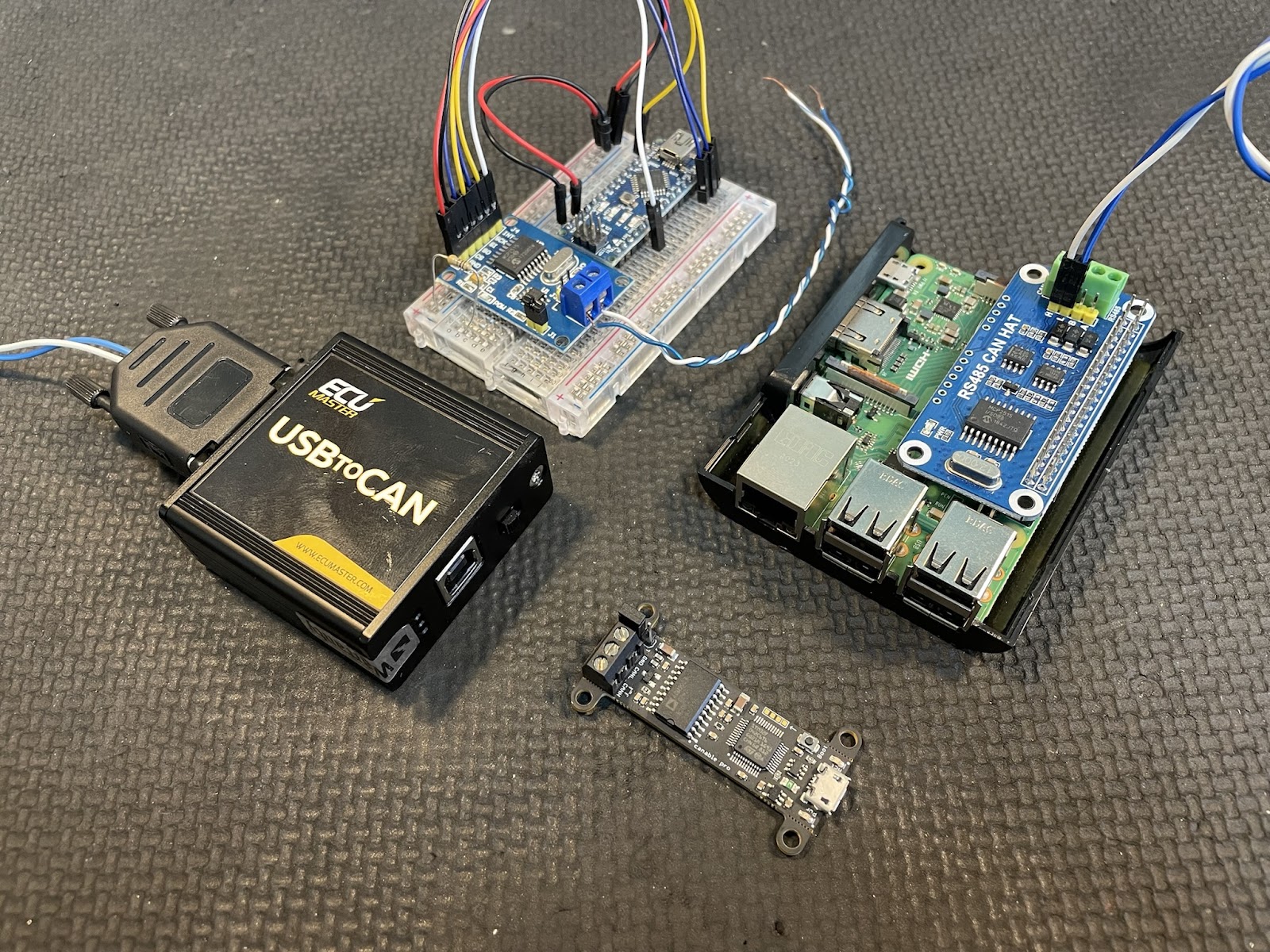
Arduino, Raspberry Pi, CANable.io and an ECU Master USB to CAN
USB to CAN setup
Let’s start by getting our computer and chosen USB to CAN device connected and operational.
I’m using the ECU Master USB to CAN for this article so the setup is rather straightforward.
Start by downloading and installing the latest version of “ECU Master Light Client” from the ECU Master website. You might need to download the USBtoCAN driver too, I didn’t need to, windows installed it automatically for me.
Connect the USB to CAN to the USB port of your computer and open the light client, choose any CANbus bitrate except auto or offline and just make sure the software opens without any errors to verify your computer is connecting to the USB to CAN device.
Once you’ve got the USB to CAN talking to Light Client on your computer, we’re ready for the next step!
CAN Wiring preparation
Now we’ve got the USB side of the equation organised, we will now focus on the CAN side.
At PT Motorsport, we prepare all of our CANbus test equipment with a DTM06-4S connector for easier integration with our CAN hubs and other CAN devices we are testing. You can forgo this step if you choose, but it does make it quicker and easier for other projects you might do in the future.
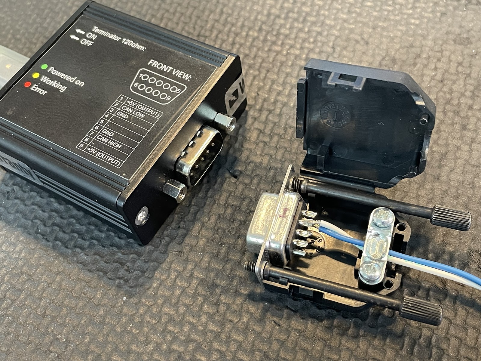
Using the supplied DB9 Connector, carefully solder a 20ga Blue wire into pin 2 and a 20ga White wire into pin 7. After soldering, make sure there are no stray conductors or solder that could join any other pins together, this will cause many errors and much frustration.
Leave the other pins unconnected.
Terminating the DB9 Connector for the ECU Master USB to CAN
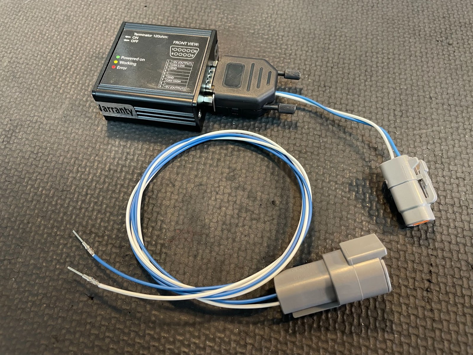
Now you can crimp on your DTM Sockets on these wires, in order to install your DTM06-4S connector. With the White wire going into position 3 and blue wire going into position 4.
Now prepare 2 more lengths of wire, one white and one blue, I’ve opted to go for 1m in length each. Crimping DTM Pins on either end. One end we will connect to a DTM04-4P Connector. The white wire going into Pin3 and the Blue wire going into Pin 4.
Now we’re left with a DB9 to DTM06-4S connection, to rapidly connect into other projects in the future and a DTM04-4P connector to flying leads, which we’ve crimped DTM pins into, for probing around our project.
Now all the hardware is ready. We can finally get connected!
ECU Master USB to CAN – Wired up to a DTM06-4S and a CAN test lead
CANbus Connection
Now we’ve got all our software and hardware ready to make a connection. Let’s find a CANbus and get on it!
Two considerations left though, first of which is the switch on the USB to CAN device, toggling this switch will connect a 120 ohm resistor between CAN high and CAN low, this is used to terminate the CANbus wiring. This can be very useful if your USB to CAN and the device you’re testing with are directly connected to each other and not part of a network, you will need to enable this switch to make the CANbus function correctly. But in the case you’re connecting to an already established and correctly designed CANbus network, you’ll want to leave the Terminating resistor Off.
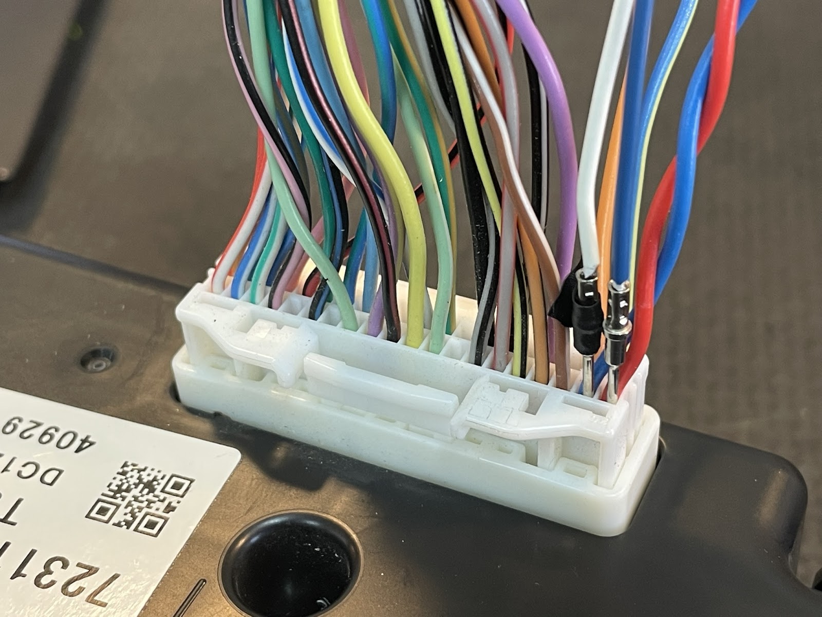
DTM pins on a test lead, back probing the CAN Wires on an AC Control unit.
Choosing the bitrate is a very easy task with the ECU Master USB to CAN. Once you’ve connected the wiring to the CANbus, open the Light client software and choose “Auto” and assuming you’ve connected your wires correctly and the CANbus is active, you’ll be greeted by all the CAN messages you were looking for. Also the bitrate displayed in the bottom left of the window.
Next, you’ll want to find out where to poke your pins into. There are a few different methods to finding the right connections and the first and most obvious one is to find any documentation for the devices you’re testing (or the devices around it) and hopefully you’ll find the pinout of the devices and connect successfully to the CANbus.
The next thing you can try is to visually inspect the device’s connectors and look for twisted pairs of wires that are not shielded, these are 9\10 the wires you’re looking for. You can test with a multimeter too.
To test with a multimeter, set your meter to DC volts and connect the common lead to ground and then probe one of the suspected CAN wires. It should be around 2.5v and if it is higher than 2.5v, maybe even approaching 3.1 volts, it’s the CAN Hi connection. If the voltage is under 2.5v, even as low as 1.9v it is the CAN Lo connection.
For a CANbus that is idle or has very low load, the voltages will be very close to 2.5v. As the data load of the bus increases, the voltages will diverge away from 2.5v. With CAN Lo getting lower and CAN Hi getting higher.
If you’ve got a Haltech ECU, you could very well connect your DTM06-4S into the CANbus port that comes with the Haltech wiring harness and be well on your way to receiving all the data the Haltech can provide.
CAN frames, streaming through into ECU Master Light Client, from a Haltech Elite 2500
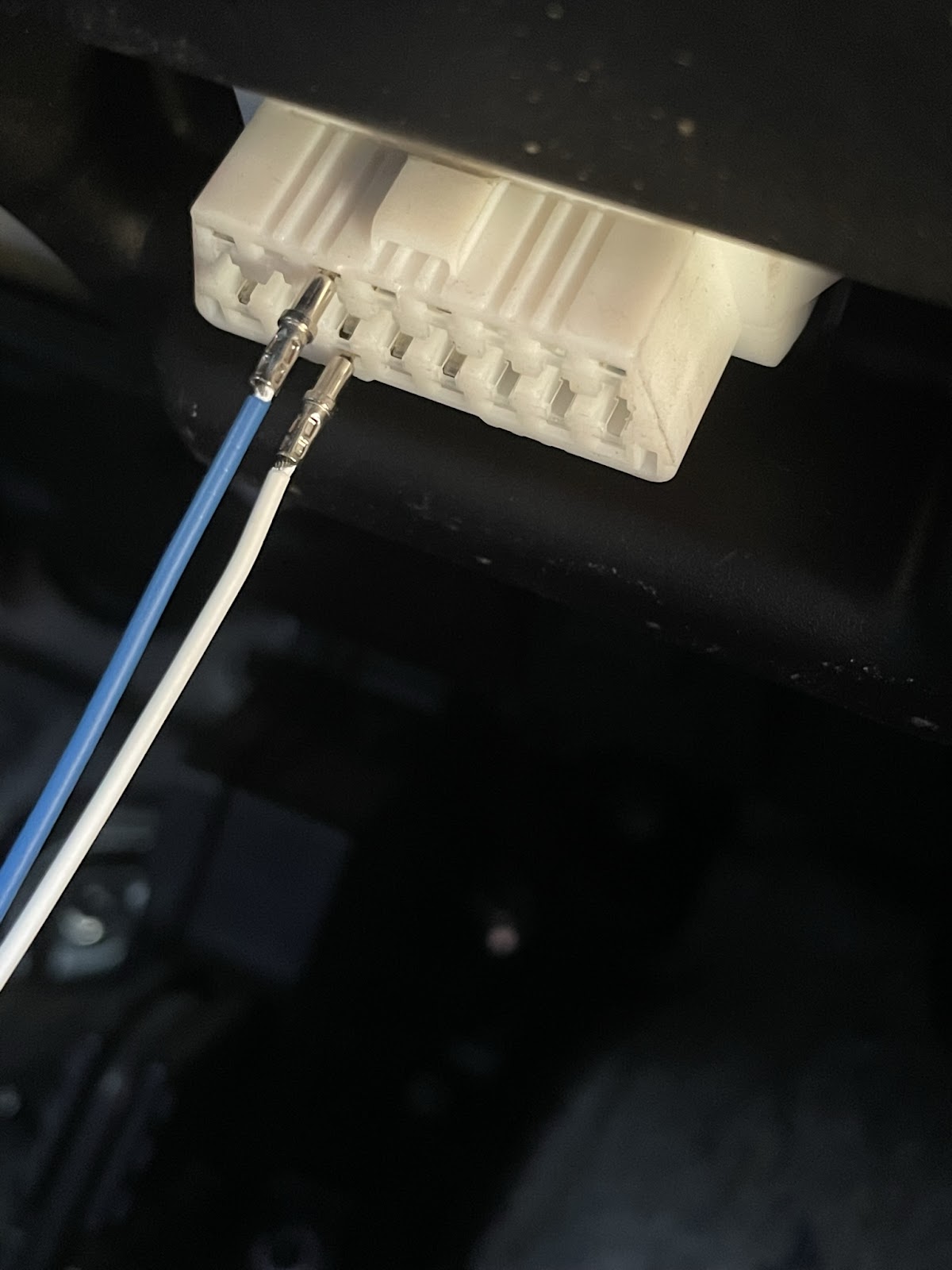
If you’re connecting to an OEM harness with the standard ECU, the OBD2 connector is a really good place to start. Using your CAN test leads, put the white wire into pin 6 and the Blue wire into Pin 14. Open up your light client and you should see the CANbus messages streaming through.
CAN Frames from a Lexus’ OBD2 port
In more modern cars though, there will be multiple CANbuses and the information you’re looking for, might be on a different bus which isn’t present at the OBD2 port, so you’ll have to extend your CANbus quest to be a little closer to the device with the information you’re looking for, eg. Steering wheel controls might be on the entertainment CANbus. Engine speed information might be found at the ECU or the Dash.
DTM Pins on a test lead connecting to an OBD2 port
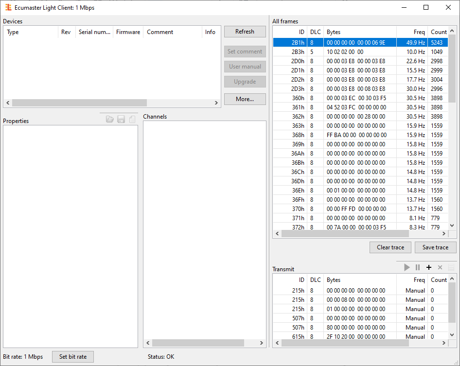
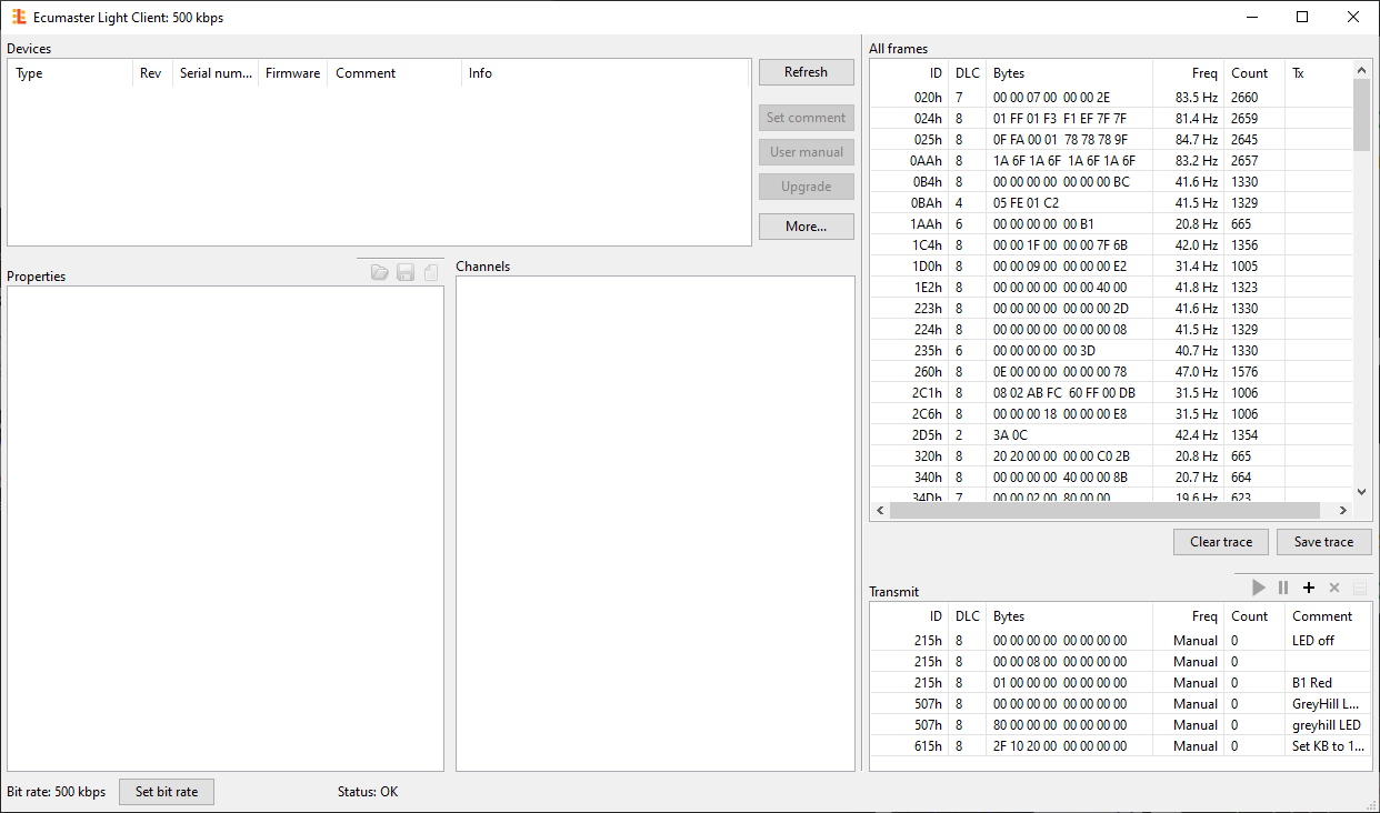
Once you’re connected and you have the Light client open, you should hopefully be able to see the CAN frames coming through in the right side of the Light Client Window under “All Frames”
If nothing is coming through, observe the lights on the USB to CAN module, they should be Green flashing and yellow on\flashing if you’re connected correctly. If the Error light is on, you might have your CAN Hi and CAN Lo around the wrong way, you could also have your bit speed set incorrectly or Termination resistors set up incorrectly. If you’re adding more devices to an existing CANbus, make sure all the devices bitrate (Speed) are set up the same, else you will have problems with your CANbus (will crash most likely and no devices will communicate) add devices in one by one if you’re having problems.
One last thing I’ll add, is with the IDs of the CAN frames.
In the light client, they’re in Hexadecimal (Base16). But some documentation and software packages will have the IDs in decimal (Base10). I’m not going to explain why here, I’ll save that for the next article, you just need to be aware of these differences in expressing the same information.
To convert from Hex to Decimal, you can use the calculator built into windows 10 and put it into programmer mode.
In light client, all the IDs have ‘h’ after the ID number, this is to illustrate to the user that the number is in Hex and the ‘h’ isn’t actually part of the ID either. You will find documentation that refers to hex numbers with an ‘0x’ in front of the number. Keep these hex and decimal numbers in mind when working with CANbus IDs and messages.
We’ll get more into hex, decimal and binary numbers in another article.
This concludes this part of the CAN Hacking journey, getting connected to the CANbus can seem like a simple step but some of the challenges are often overlooked. Hopefully this article can help you with your project!