Description
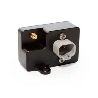
MCE18 stands for “Multifunction Can Bus Extension” with formerly 18 connections (now 19) – why is this module needed?
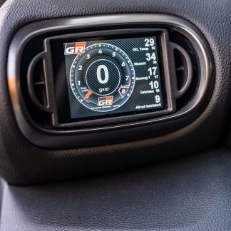
Our displays ( MFD15 , MFD28 , MFD32 ) have four analogue inputs. In some applications, however, this may not be enough and you need more inputs.
It makes sense to map this using the flexible Can Bus protocol. For this purpose, the sensors are connected to our MCE18 and sent via CAN bus to the device to be received – e.g. one of our displays.
But even freely programmable control units only have a limited number of inputs. This can be easily expanded with our module and sent directly to the control unit.
9 analog inputs (0-5V)
8 digital inputs (on/off) (up to 5V)
3 digital outputs (on/off LOW SIDE 0.5A) (new in v2!)
Tested with:
CAN checked MFD28/MFD32/MFD32S
MaxxECU
Ecumaster
LinkECU
Haltech (emulates an IO Extender A+B or just B)
Syvecs (coming soon)
Motec (coming soon)
aim
This device is also available without a housing: CFE18 – can switch board
– Hardware –
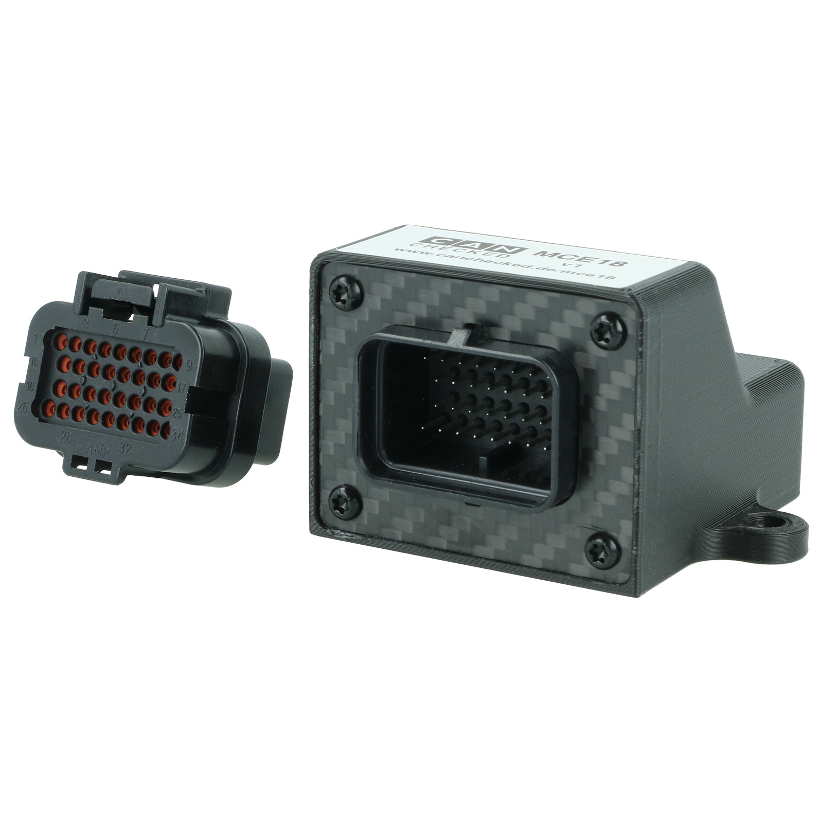
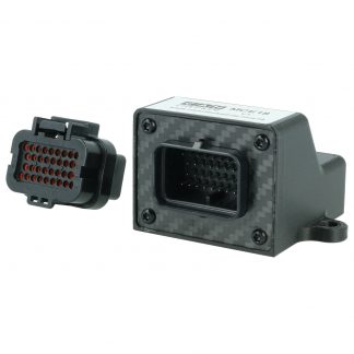
The MCE18 kit includes:
- MCE18 with case
- Connector Superseal 34pin (TE 4-1437290-0)
- Pins Superseal 1.0 20AWG (TE 3-1447221-4)
- 3 jumpers


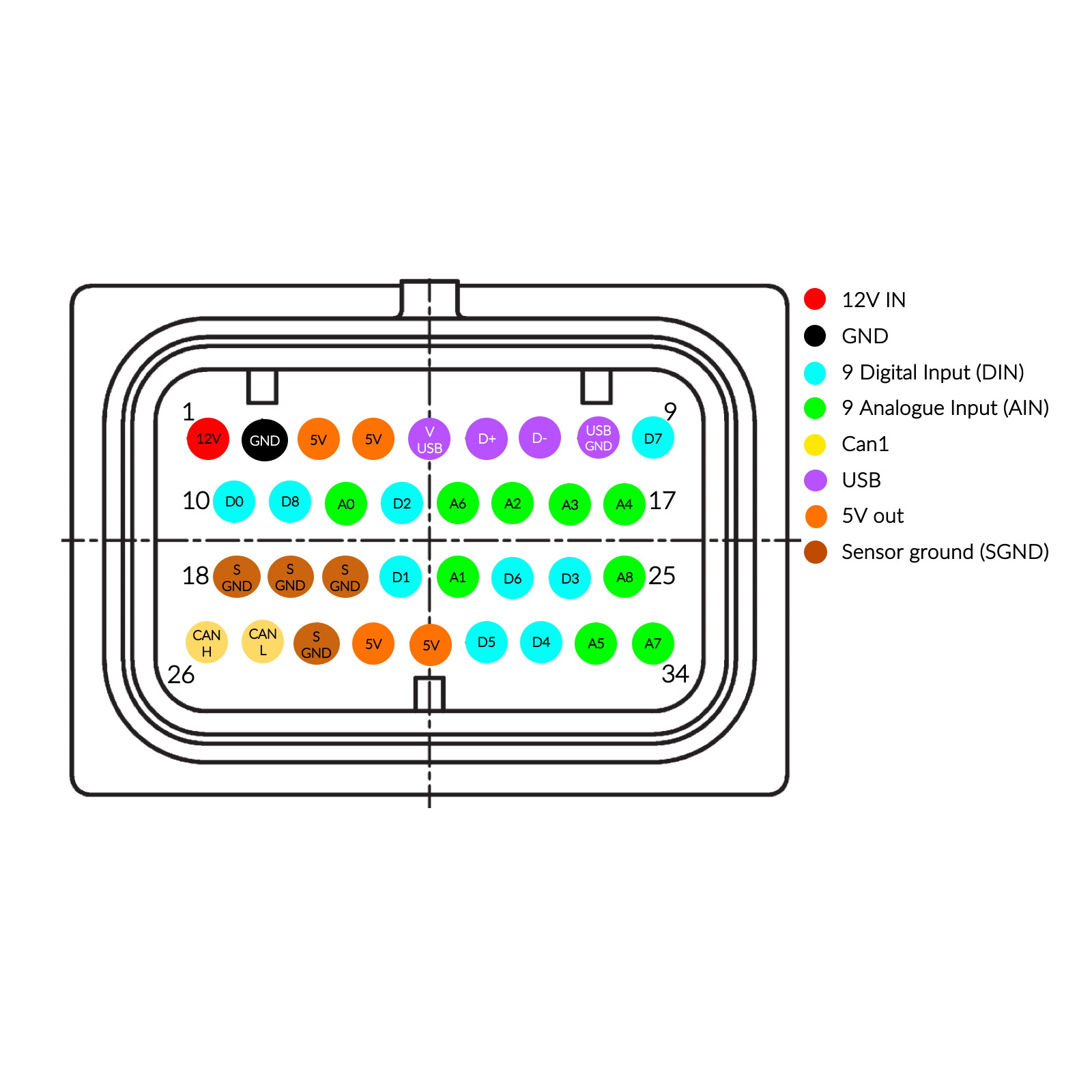
– Pin assignment –
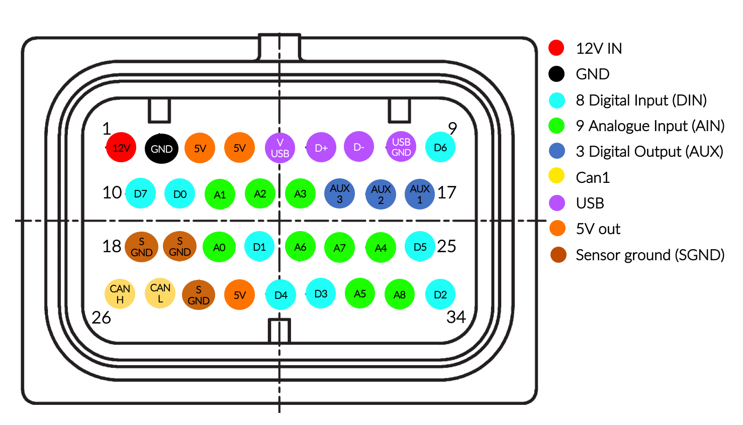
There are versions of the MCE18 where the connector is rotated and the locking tab is on the bottom. Please note that the 12V pin is always on the top left of the device.
| Pin code | Designation | Description |
| 1 | +12V | 12V power supply |
| 2 | GND | Ground power supply |
| 3 | +5V | 5V sensor power supply |
| 4 | +5V | 5V sensor power supply |
| 5 | VBUS | 5V USB (usually red) |
| 6 | D+ | D+ USB data (usually green) |
| 7 | D | D- USB data (mostly white) |
| 8th | USB GND | USB ground (usually black) |
| 9 | D6 | Digital input 6 |
| 10 | D7 | Digital input 7 (unassigned in v2 – board v0.8) |
| 11 | D0 | Digital input 0 |
| 12 | A1 | Analog input 1 |
| 13 | A2 | Analog input 2 |
| 14 | A3 | Analog input 3 |
| 15 | AUX3 | Digital output 3 |
| 16 | AUX2 | Digital output 2 |
| 17 | AUX1 | Digital output 1 |
| 18 | SGND | sensor mass |
| 19 | SGND | sensor mass |
| 20 | A0 | Analog input 0 |
| 21 | D1 | Digital input 1 |
| 22 | A6 | Analog input 6 |
| 23 | A7 | Analog input 7 |
| 24 | A4 | Analog input 4 |
| 25 | D5 | Digital input 5 |
| 26 | CANH | Can Bus High |
| 27 | CANL | Can Bus Low |
| 28 | SGND | sensor mass |
| 29 | +5V | 5V sensor power supply |
| 30 | D4 | Digital input 4 |
| 31 | D3 | Digital input 3 |
| 32 | A5 | Analog input 5 |
| 33 | A8 | Analog input 8 |
| 34 | D2 | Digital input 2 |
– Jumper configuration –

If you remove the front 4 screws, you can pull off the housing. There are three jumpers on the back.
1) JP1 plugged in activates the 120 Ohm resistor for the Can Bus
2) JP2 plugged in activates the 1K1 pull-up resistor for A1 and A2
3) JP3 plugged in activates the 1K1 pull-up resistor for A6 and A7
By default, all jumpers are removed
Configuration Details
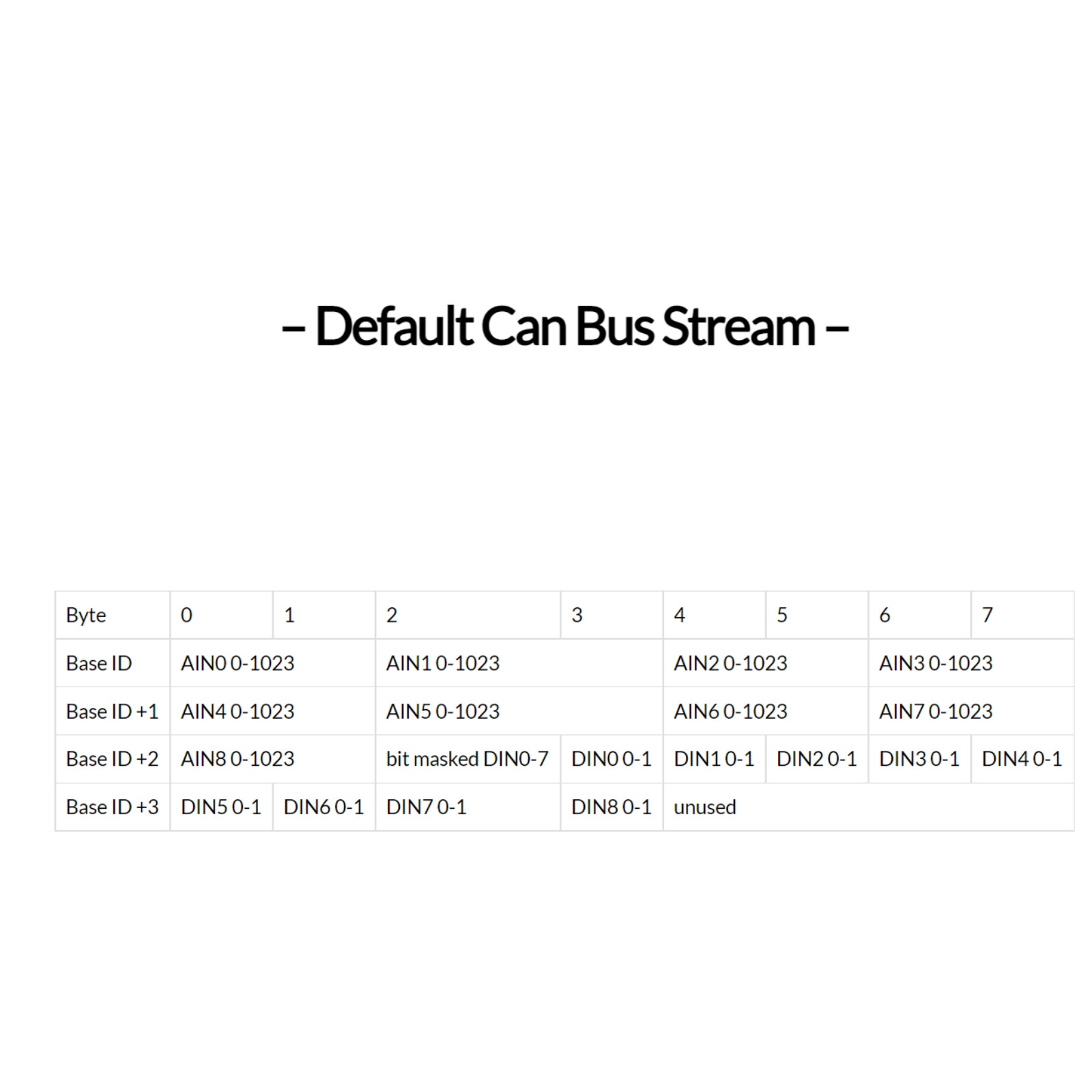
– Default Can Bus Stream –
**Specify your ECU at checkout and we’ll configure your device before shipping**
The data of the inputs are queried and transmitted every 50ms (20Hz – changeable). The data is transmitted as “unsigned big endian”.
As soon as 12V and ground are connected, the green status LED on the back lights up.
Can Bus ID: 0x700 ( Base Data CAN ID – changeable)
| byte | 0 | 1 | 2 | 3 | 4 | 5 | 6 | 7 |
| BaseID | AIN0 0-1023 | AIN1 0-1023 | AIN2 0-1023 | AIN3 0-1023 | ||||
| Base ID +1 | AIN4 0-1023 | AIN5 0-1023 | AIN6 0-1023 | AIN7 0-1023 | ||||
| Base ID +2 | AIN8 0-1023 | bit masked DIN0-6 |
bit masked AUX1-4 |
N/A | N/A | device chip temperature |
release=4 | |
MCE18 TRI File Download MCE18/CFE18 Tri File
MCE18 DBC File Download MCE18/CFE18 DBC File
The configuration or modification of the Can Stream is described in CFE18 – Can Bus Function Extension .
– AIN smoothing –
If the analog inputs fluctuate too much, they can be smoothed out using software. This can be configured separately for each analog input.
The higher the smoothing, the quieter (smoother) the value becomes, but it also reacts more slowly to fluctuations. You have to find a healthy middle ground here.
Values go from 0-249 – the higher the more smoothing, 0= no smoothing, default: 160
The setting is made via Can Bus – see CFE18 => ” Configuration options ”
– Digital Outputs –
The MCE18 has three digital outputs in the v2. These can be loaded up to a maximum of 500mA and switch to ground (LOW SIDE).
To do this, a Can Bus frame is sent every 100ms (CAN Id can be configured here – from a 500ms pause between the frames, the timeout is activated and the outputs are deactivated): (
0=inactive, 1=active)
| byte | 0 | 1 | 2 | 3 | 4 | 5 | 6 | 7 |
| CAN RX ID (default: 0x640) | AUX1 0/1 |
AUX2 0/1 |
AUX3 0/1 |
unused | ||||
The setting is made via Can Bus – see CFE18 => ” Configuration options ”
– Control unit / ECU configuration –
**Specify your ECU at checkout and we’ll configure your device before shipping**
The analog inputs provide a 10-bit resolution and therefore values from 0 to 1023. The value must be converted in the control unit. All values are “unsigned big endian”
Examples:
5V voltage AIN0
0x700 Byte0+1
Multiplier: 5; divisor: 1023; Offset: 0
or multiplier: 0.004887585533
Exhaust gas temperature (type k) AIN7:
0x702 Byte6+7
Multiplier: 1250; divisor: 1023; Offset: 0
or multiplier: 1.2218963832
Either the individual bytes are used for the digital inputs. Eg DIN6: 0x702 byte 6 or the bit mask at 0x702 byte2
eg DIN6: 0x702 Byte2 Mask:0x40
Here is a little cheat sheet to do the calculations for a MaxxECU: maxxecu-sensor-calculation.xlsx
– Documentation / download –
**Specify your ECU at checkout and we’ll configure your device before shipping**
MCE18 TRI File Download MCE18/CFE18 Tri File
MCE18 DBC File Download MCE18/CFE18 DBC File
MCE18 MaxxECU File Download MCE18/CFE18 MaxxECU File





Reviews
There are no reviews yet.