There are a few tools mentioned in the following how-to, they can be purchased right here at PT Motorsport.
-
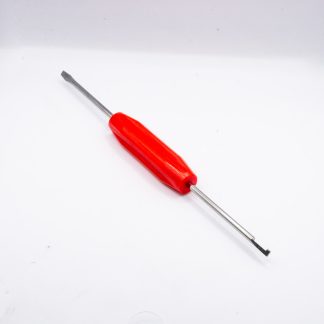 DE-DET-RT1 Removal Tool Combo$25.38
 -
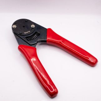 Deutsch Connector Crimping tool$48.00
 -
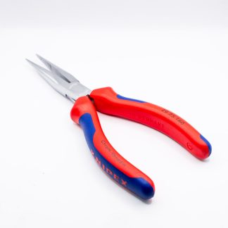 Knipex – Telephone pliers$89.00
Crimping
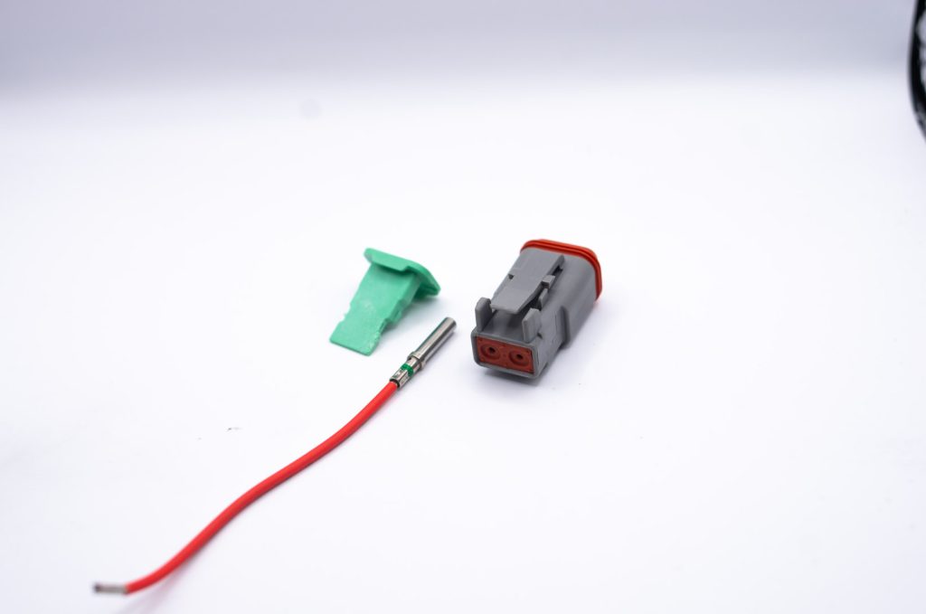
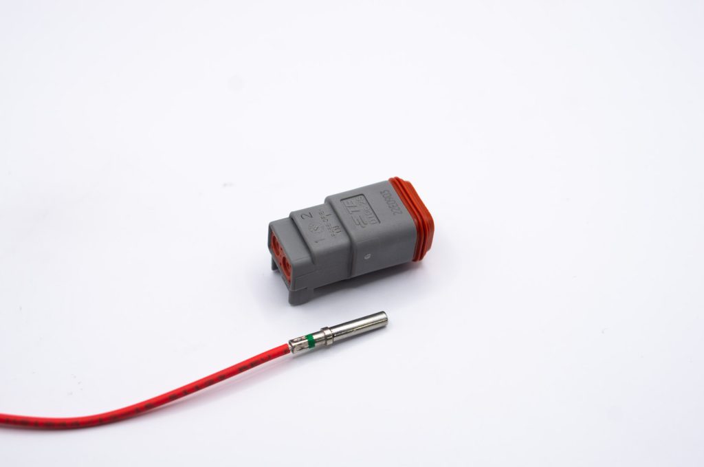
- Prior to performing your crimp, you will need to ensure that your Deutsch connector is appropriate for the wire you are using.
As this crimp was being performed on 16AWG wire a DT connector was selected.
The Green band on the terminal means that is is the larger size and can accept 14AWG wire.
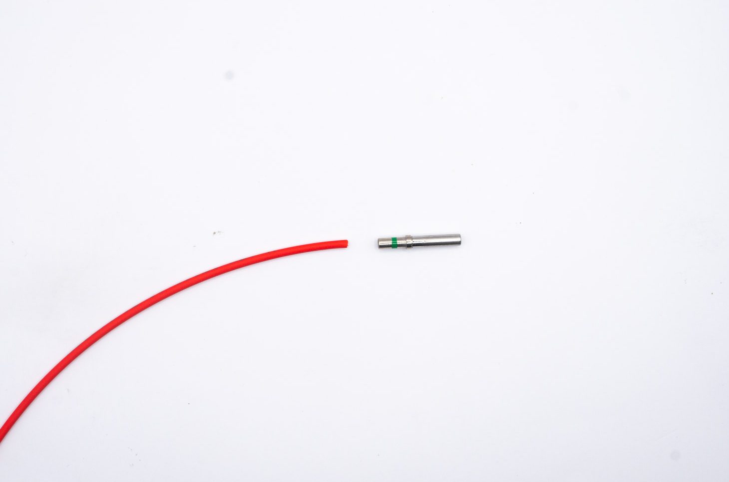
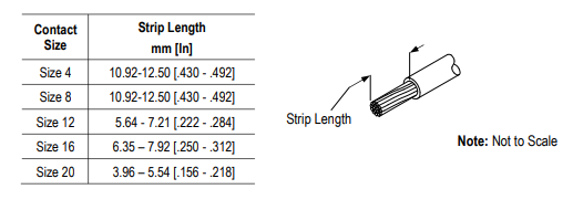
2. The wire is then stripped. The length of the strip will depend on the contact being used.
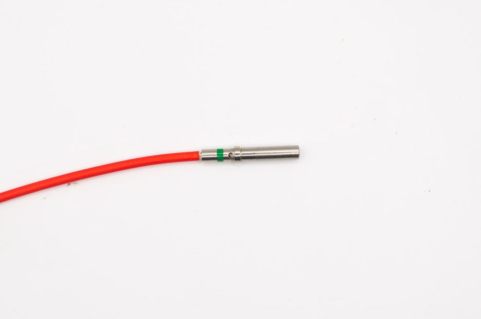
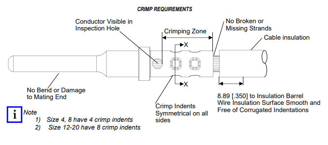
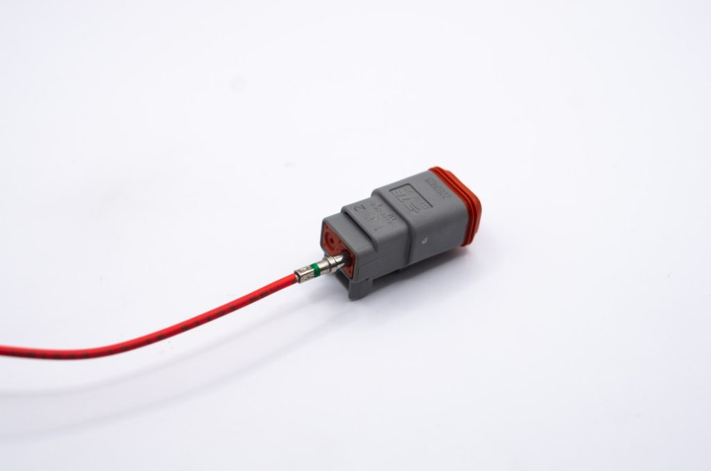
As you can see our stripped wire is visible through the inspection hole, and there is a gap between the insulation and the contact.
Stripping the wire is a step where many mistakes can be made.
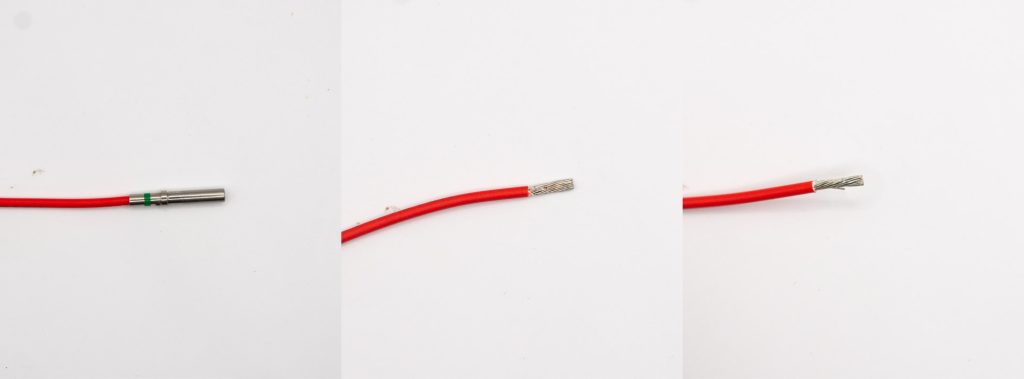
When checking the strip length, place your stripped wire into the connector. A good rule of thumb is that the distance between the insulation and the contact should be no smaller than a fingernail’s thickness and no greater than the width of the wire.
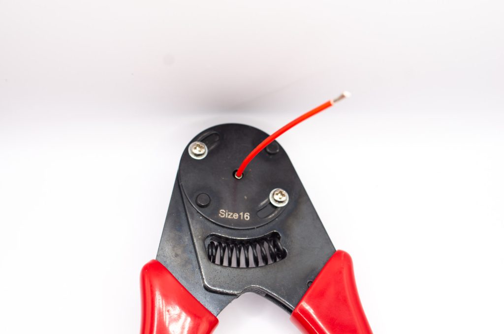
3. Insert the contact into your crimping tool.
As this crimp was a #16 pin for a DT connector, a DET16 tool was selected.
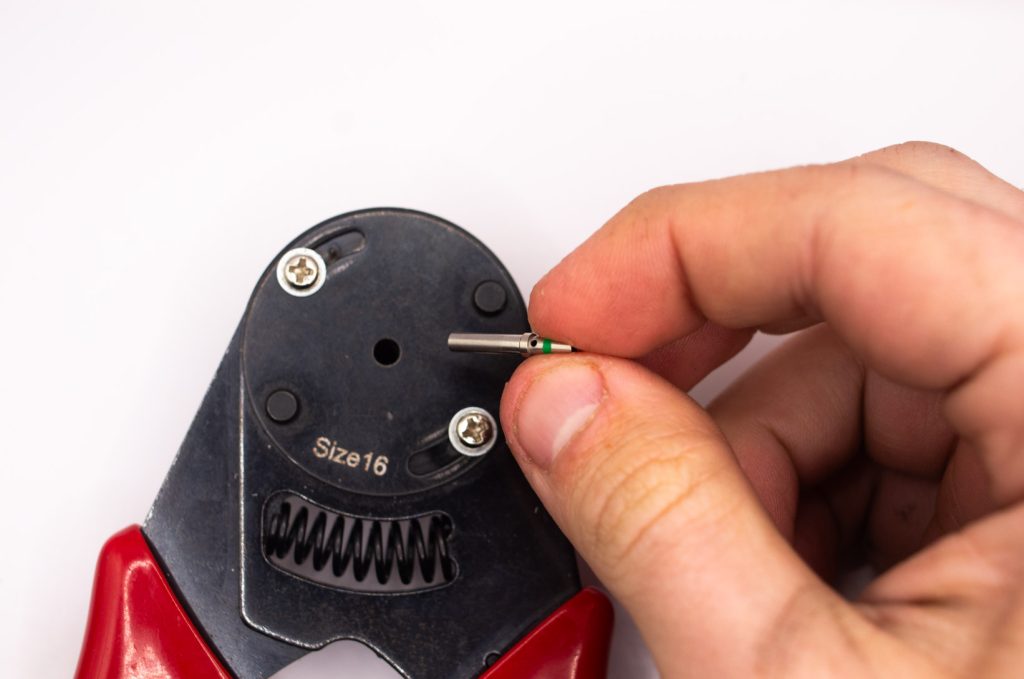
Ensure the contact is inserted the correct way into the crimp tool, with the mating end entering first.
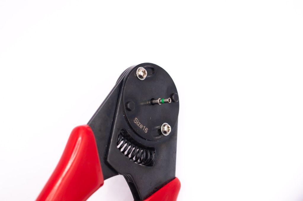
4. Insert your wire into the contact.
Compress the handles of your crimp tool to complete the crimp.
Ensure that the crimp tool is fully depressed before releasing the handles.

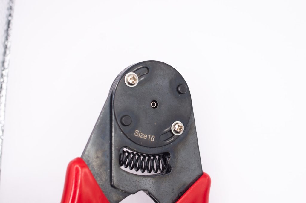
5. Remove your wire with its completed crimp.
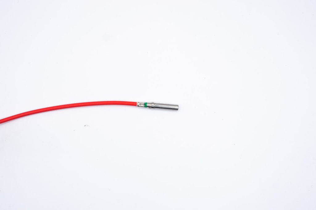
Ensure that your crimp meets all of the following requirements.
Inserting Contacts and Wedgelocks
1. Take your contact and connector housing .
Insert the contact into the back of the connector housing through the rear grommet.
Push the contact until a click is felt.
Gently pull back to confirm the contact is locked in place.
2. Once you have inserted your contacts insert the wedgelock.
Ensure the holes in the wedgelock line up with the contacts in the connector.
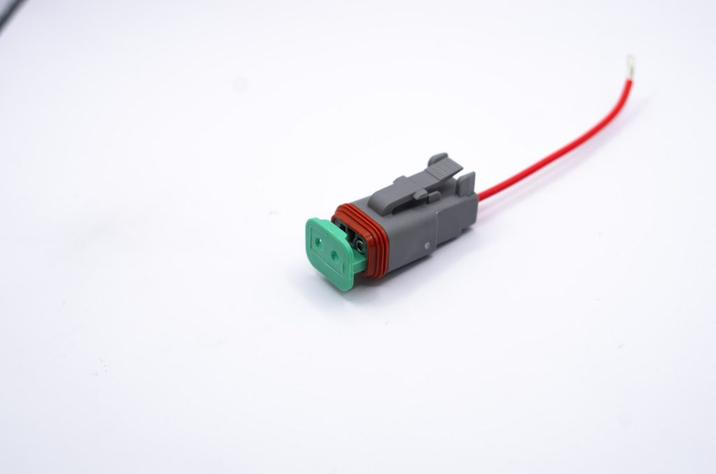
Push until a click is felt.

Insert a cavity seal into any vacant positions in your connector and your connector is now ready to use.
Removing Contacts and Wedgelocks
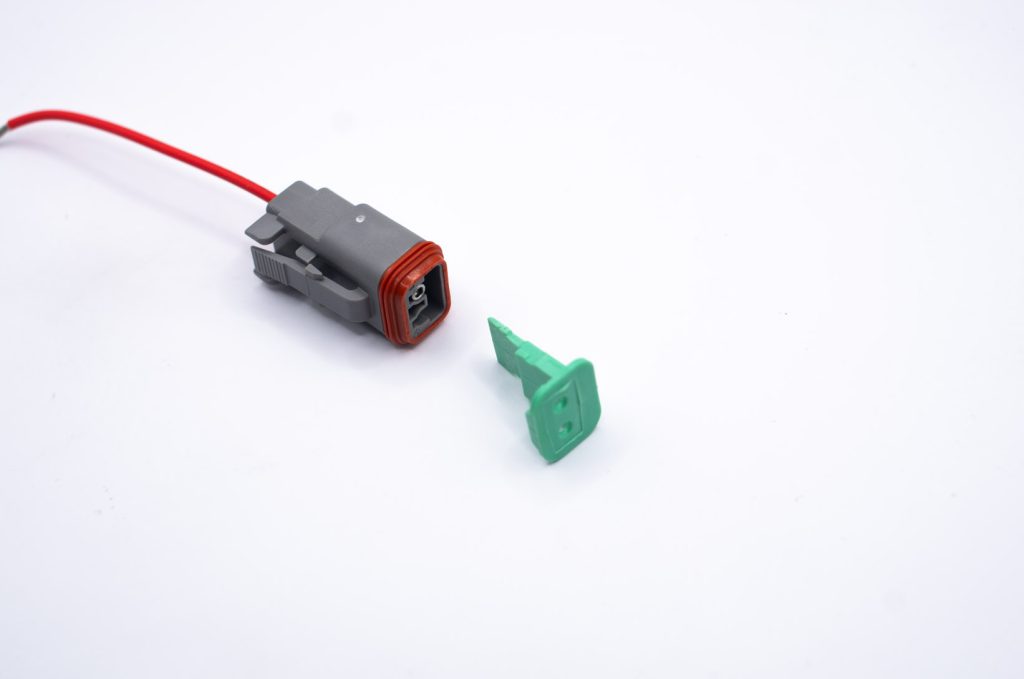
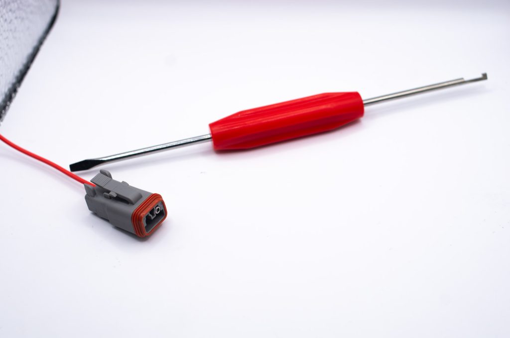
1. To remove the wedgelock and contacts a pair of Knipex Telephone pliers or a DET RT1 Removal tool combo is helpful to remove the wedgelock.
Simply pull on it to remove it.

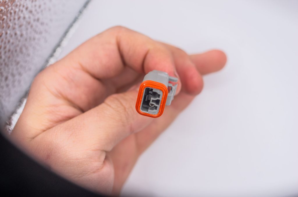
Next, press the locking tab out of the way, this is made very easy with Telephone pliers or the RT1 tool.
You can see the locking tab in the image below.
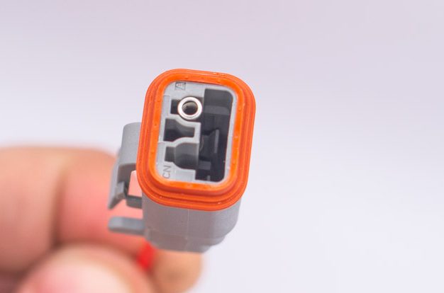
The tab needs to be pressed out of the way so the contact can be removed.
Insert your tool of choice into the front of the connector.
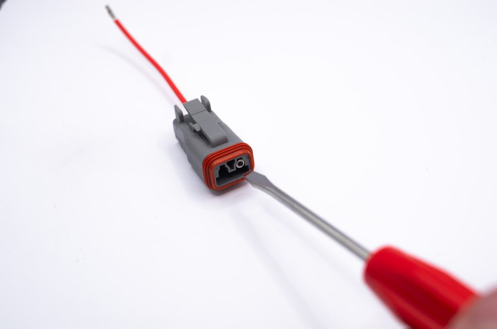
Push the locking tab away from the contact.

As you push the tab out of the way, gently pull on the wire to begin removing the contact.
Once the initial ridge is passed the tool can be removed and the pin is able to be fully removed.