When adding sensors, or configuring an ECU you will often need to input calibration data so that the ECU knows which input values represent what data.
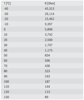
Often calibration tables will be available in ohms like this example from a Bosch Motorsport coolant temperature sensor
For some ECUs this is fine as you can select between units when inputting a calibration table
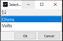
If this isn’t an option you can manually calculate the voltage using ohms law

Unfortunately this takes a lot of time to do manually, and if using a pullup resistor adds more complexity.
Fortunately, with a little bit of spread-sheeting know-how you can create an automatic voltage calculator with the ability to change the sensor input voltage and pullup resistor value on the fly. The below link is to the PT Motorsport sensor calibration converter.
PT Motorsport Sensor Calibration Converter
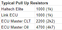
We have included conversion tables for some common sensors, as well as the pull-up resistor values used by some common aftermarket ECUs.
If you need to convert your own sensor calibration you will need to first download the document so that you can edit it.
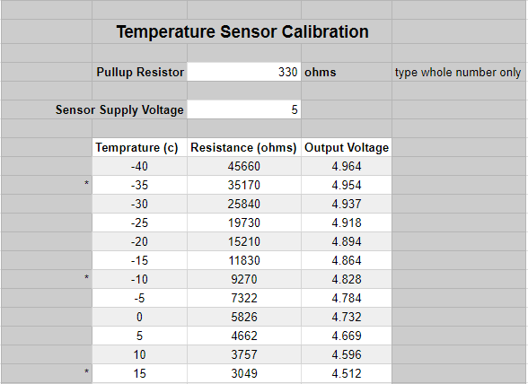
The main section of interest is the grey table. This has the sections for altering the pullup resistor and sensor supply voltage values as well as the sensor calibration data.
For the pullup resistor value you can either input the value you intend to use, or if you are using an ECUs internal pullup resistor you can input the value. The table includes some of the common ECU pullup resistor values. If you are unsure which pullup resistor to use, or want to know more about why we use them, read this article.
You can also enter the sensor supply voltage. In most automotive applications this will be 5V.
Finally, enter the sensor calibration data.
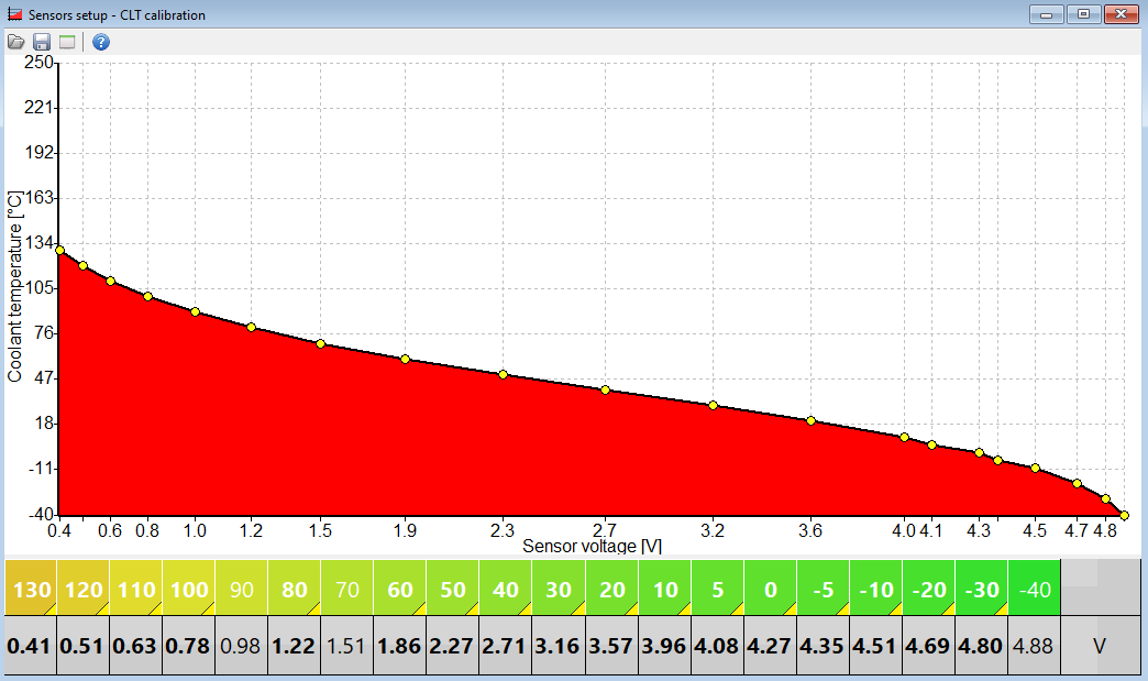
Using the example Bosch sensor above and using it with the internal pullup resistor in a Haltech ECU we can input the following data. Where there isn’t enough data to fully complete the table you can simply remove those rows.
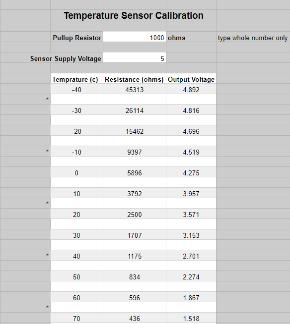
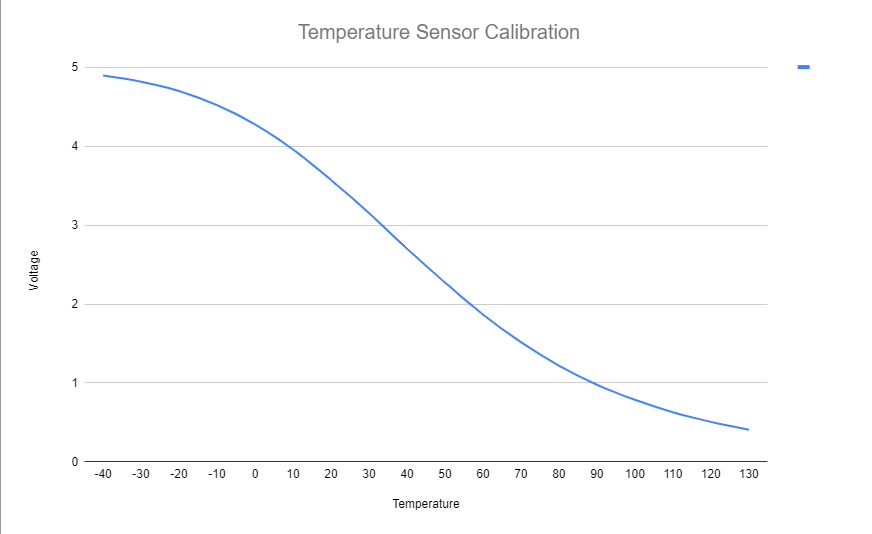
As the data is entered the table will update, giving the correct output voltage values. Along with the table, a graph is also generated. This graph is useful to determine whether your pullup resistor is suitable for your application. For more information on why we use a pullup resistor, and how to choose the correct one for your application see our article.
With this data we can input the values into our ECU calibration table
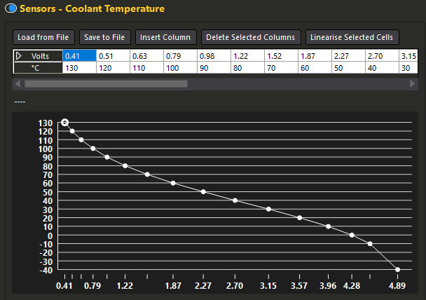
This will look different across ECUs, the below is from the ECU Master EMU Black software, but using the same values (for this example that would mean wiring in a 1000ohm resistor rather than using the internal 2200ohm)