Posted on

Designing a custom thumb-throttle for a desert racing KTM quad bike.

When your KTM 525XC Quad bike isn’t already bonkers enough and you’re looking for the versatility of EFI over carbureted then you obviously swap in the engine from a KTM 690. They’re both KTM, should be simple right?

For engine control, an ECU Master EMU Black was selected.

A housing was used to ensure that the ECU was protected from the harsh elements encountered in the desert and during racing. This enclosure houses the ECU, a fuse box, and a map switch. The map switch is used to switch the startup fuel, fuel target map, and ignition table within the ECU.

Most components are fairly plug and play, especially with a custom wiring harness being constructed, however finding an accelerator position sensor (APS) which was appropriate proved difficult.

We initially started with a Volvo APS, but it used a rather unique output system. As the accelerator position changes the voltage goes from 0 volts, up to 5 volts and then back down to 5 volts. Unfortunately due to this rather unique approach we couldn’t set it up to work with the ECU Master.

Next we looked at some OEM thumb throttles. These generally run a cable to the throttle body and use a single potentiometer to generate their voltage output. As the cable will physically pull the throttle shut in the event that the potentiometer fails this has an effective failsafe built-in. Unfortunately for us there weren’t any off the shelf alternative OEM solutions which would work with the packaging constraints that we had to work with.

In the end we turned to modification, using the original KTM ATV thumb throttle and creating a custom solution to allow it to accept the APS from a Yamaha YZF-1. The Yamaha APS was chosen due to its dual potentiometer design, meaning it has a failsafe built in. As this quad is going to be used for desert racing, the chances of dust ingress into the APS is far higher than on a road-going vehicle.

In order to fit the Yamaha APS a “key” was designed which converts the key on top of the axle within the KTM throttle assembly into the keyed hole in Yamaha APS.

The Yamaha APS uses a “following” type of signal, with both potentiometers going from 0-5V as the accelerator travel is increased. To use this style within the EMU Black we selected the Honda FN-2 check type for the failsafe check type.

To secure the “key” a 3D printed part was created to house the APS, and form a cover for the throttle. To mount this to the throttle M5 heat inserts were used. The part itself was designed in Fusion 360 with the base of the part created using a flat-bed scanner and the rest being added manually with caliper measurements.

The original throttle plate also got a 3D printed insert to stop dust and dirt ingress.

The 3D printed components were printed our new BambuLabs X1 C printer with the PT Motorsport logo being added using the AMS system.

Posted on

Haltech Wideband CAN sniffing and DBC files

This project began as a way to determine how the Haltech Wideband responded to received information on the CANbus. You can read more about that in the “Using a Haltech Wideband Controller with Link and ECU Master Black ECUs” article.

Using a combination of ECU Master Light Client and Savvy Can the can messages were viewed to determine which streams were relevant to the WB1.

The PC connection was done using a Kvaser Leaf Light V2, but if you’re interested in trying something like this yourself our “CANbus Hacking – Part 1 – Getting on the CANbus” article is a great place to start.

With only the WB1 plugged in, the streams looked like this:

While viewing the CAN stream we could look for patterns and changes. Once we knew which streams were being broadcast by the WB1 we could connect a Haltech ECU and open NSP. This allowed us to use the WBC1 WBI Lambda channel to display the state of the WB1. Using this we could see which CAN messages changed at the same time as the NSP display.

From this, we could disconnect the WB1 from the CANbus and transmit our own stream to see which numbers had what effect on the data received by the NSP software.

Sending the above on the CANbus resulted in this display in the NSP software

Using a similar process we were able to determine the following information about the WB1 CAN stream

CAN ID: 0x2B1

CAN ID: 0x2B3

If you read those tables carefully you would have noticed that the battery voltage conversion is a ridiculous number, however it does provide an accurate battery voltage output. Wondering whether the WB1 itself was seeing a voltage that was different to the battery output we tried taking it apart, but unfortunately the PCB is potted into the housing so we couldn’t check this.

With this information the we could create a DBC file within SavvyCAN

The DBC allows you to view a “translated” version of the CAN stream, giving something like below

This type of data can be used when integrating these devices with other ECUs, or when creating your own CAN based devices such as our “Arduino Nano powered gauge for the Haltech WB1“.

  • Haltech WB1 Bosch - Single Channel CAN O2 Wideband Controller Kit HT-159976
    Haltech WB1 Bosch – Single Channel CAN O2 Wideband Controller Kit HT-159976
    $495.00
  • 4 Port CAN Hub
    4 Port CAN Hub
    $99.00$108.18
  • USB-CAN Interface
    USB-CAN Interface
    $195.00

DBC files for the WB2 will be updated at a later date.

Posted on

Using a Haltech Wideband Controller with Link and ECU Master Black ECUs

The Haltech CAN Wideband Controller Kit is an all in one wideband solution with plug and play functionality with Haltech ECUs. After seeing online that you could add heater control functionality while using them with Link ECUs I decided to delve deeper into it and check whether this was really the case.

To give some back story, some other ECU brands also have cross-compatibility with the Haltech Wideband Controllers. Two of these are:

Link (G4+, G4X, G5)

ECU Master (Black)

At this point I had planned to have the instructions for how to set up the Haltech WBOs on each of the above ECUs. Instead of blindly trusting the internet, I decided that I hated having spare time and jumped into confirming whether the CAN heater controls actually worked.

Cue an absolutely giant rabbit hole of CAN sniffing, wideband sensors, and ECUs.

The original premise of this article was to let people use a Haltech WBO with other ECUs and retain proper heater functionality. I believed this to be a fairly simple endeavour involving a little bit of CAN setup. As I understood it, the Haltech WBO uses the engine RPM signal being sent via CAN to determine what the engine state is and to therefore control the wideband sensor.

With that in mind I tried the following setups:

The ECU Master Black software allows you to select the Haltech CAN Wideband controller straight from the Oxygen Sensor Menu

Once connected if you output a Haltech V2 CAN-bus dashboard stream the engine rpm will be broadcast on the correct CAN ID for the WB1.

The Link is slightly more involved. In the CAN setup menu, the Mode must be set to user defined. A channel must then be set to “Link CAN-Lambda” with the CAN ID set to 950.

With this done, the Link will receive the Lambda data from the Haltech, but the wideband heater will always be on when the ECU is on.

To change to a setup with an RPM lockout so that the heater is only on once the engine is started the following CAN channel needs to be added.

On a separate Channel, change the mode to “Transmit User Stream 1” with a transmit rate of 50 Hz and a CAN ID of 864.

Once this is done, a custom stream must be set up.

Add a Frame, make sure the Frame setup is as follows
Frame Size: 8
ID Position: None

Then add a Parameter and select “Engine Speed”

What next?

After doing the above on both a Link and an ECU Master Black ECU with a Haltech WB1 plugged in we found that there was no difference in how the controller behaved.

Upon turning the car on (without starting the engine) the wideband heater was immediately on (drawing 1.4-1.6 amps). This isn’t what we expected at all, so we went back to basics and did the same test with the WB1 plugged into a Haltech Elite 2500. Expecting a different result, the wideband behaved in exactly the same way, heating up immediately irrespective of the engine state.

In doing all of this, the CAN stream from the WB1 was sniffed as well to try and determine what state the wideband was in. For a more detailed write up on that, see our “Haltech Wideband CAN sniffing and DBC files article.

In summary, the Haltech Wideband controllers are an excellent option for use with other ECUs, but their behaviour didn’t quite match what we were expecting and as a result, setting them up with another ECU is even easier as the engine output CAN messages made no difference to how they behave. This also means that they can be run as a standalone unit without any ECU involvement if you just need to add a wideband sensor/controller and would like to be able to upgrade at a later date. If that is the case then you can add a standalone Arduino powered gauge to monitor your wideband readings, to find out more about that jump over to our “Making an Arduino Nano powered gauge for the Haltech WB1” article.

  • Product on sale
    CANbus IO Expander - Nano
    CANbus IO Expander – Nano
    $49.00
  • Haltech WB1 Bosch - Single Channel CAN O2 Wideband Controller Kit HT-159976
    Haltech WB1 Bosch – Single Channel CAN O2 Wideband Controller Kit HT-159976
    $495.00
  • 4 Port CAN Hub
    4 Port CAN Hub
    $99.00$108.18

The CAN sniffing and testing was performed on a Haltech WB1 with Firmware Version 1.9 and 2.3

Posted on

Making an Arduino Nano powered gauge for the Haltech WB1

In some motorsport disciplines, the use of data loggers is prohibited, but the use of live gauges is not. That’s how this project came into existence.

The goal was to have a standalone gauge that worked with a Haltech WB1 without needing a Haltech ECU.

The basis of this board was a PT CAN IO mini, but the same result can be achieved using an Arduino Nano and an MCP2515 module.

Using a 1.3in OLED screen a display layout was decided upon which allowed for all the information required to be easily viewable. The main data we are interested in is the Lambda itself, so it is the largest text and in the centre of the screen. We are also interested in the Wideband sensor state as this is useful for diagnostic purposes. As the sensor state is only needed when the Lambda value is zero, the Lambda text is replaced with the sensor state.

How the display looks when a Lambda of 1.02 is sent by the WB1
How the display looks when the lambda value is 0 and the sensor is in the condensation phase.

To program the arduino we used the information in the “Haltech Wideband CAN sniffing and DBC files” article to know which CAN IDs we needed to watch, as well as which bytes we needed for each piece of information.

Once the gauge was working correctly it was time to add a startup screen (because who doesn’t love a bit of flair). Using the image to cpp converter found here:

https://javl.github.io/image2cpp/

A bitmap was generated for the PT logo. The logo was resized to correctly fit the 128×64 pixel screen.

With the bitmap generated the startup image should be simple enough to implement, but due to some idiosyncrasies of the Nano the image always appeared incorrectly. To solve this, the image needed to be stored in the SRAM rather than the flash memory, this meant that the logo had to be as small as possible to ensure there was enough memory left for the program.

The display in the startup phase.

To also help with diagnostics, when the correct CAN message is not received the display shows that there is a CAN error.

The display showing a CAN error.

If you are interested in making your own standalone WB1 gauge, or in making a similar project, the project files can be found on GitHub

https://github.com/ptmotorsport/HaltechWB1_CANGauge

A 3D printable 52mm gauge mount is currently being designed and will be available as a purchasable enclosure or a printable file once complete.

  • Product on sale
    CANbus IO Expander - Nano
    CANbus IO Expander – Nano
    $49.00
  • MCP2515 CANbus Driver Module for Arduino
    MCP2515 CANbus Driver Module for Arduino
    $9.90
  • 4 Port CAN Hub
    4 Port CAN Hub
    $99.00$108.18
Posted on

Engine Protections

A lot of OEM vehicle engine management systems lack proper forms of engine protection, with nothing more than a “low oil pressure” light. Usually in cases where the light comes on, it’s too late for the engine. While engine protection isn’t as exciting as big turbos and bulk power, it is a crucial part of the longevity of your engine. Whether you have a stock engine or a fully built performance motor replacing an engine uses time and money.

There are multiple types of engine protections which will be detailed below.
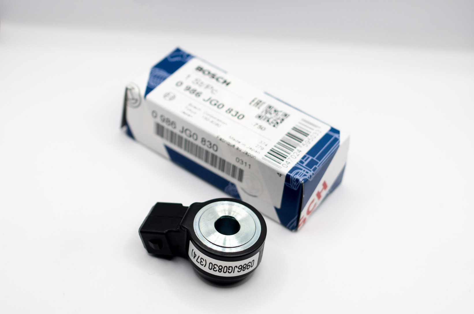
Knock

Knock sensors are crucial to ensuring an engine is running safely. Knock sensors are used to measure noise coming from the engine, and are used to detect detonation or “ping”. Detonation is when fuel is ignited by the combustion and heat from the cylinder rather than the spark event. This ignition is not only at the wrong time during the engine cycle, but it also has a less smooth explosion. As detonation can very rapidly cause damage to pistons, valves, cylinders, and heads it is important that it is kept under control.

Oil Pressure

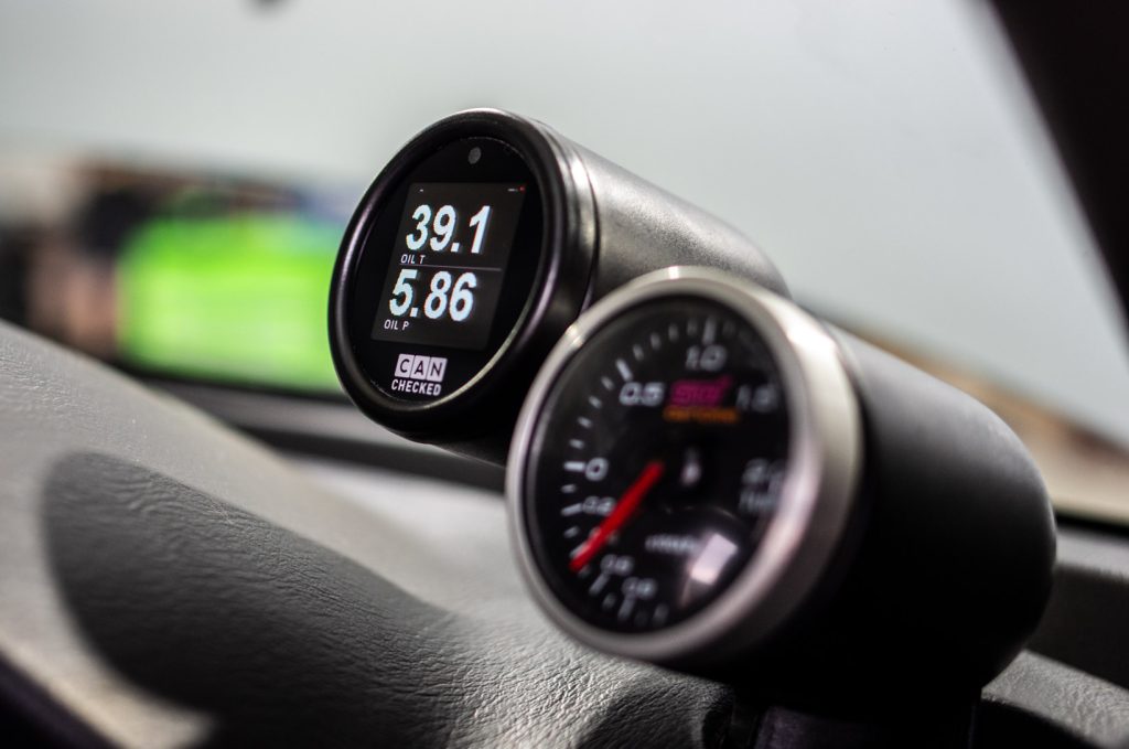
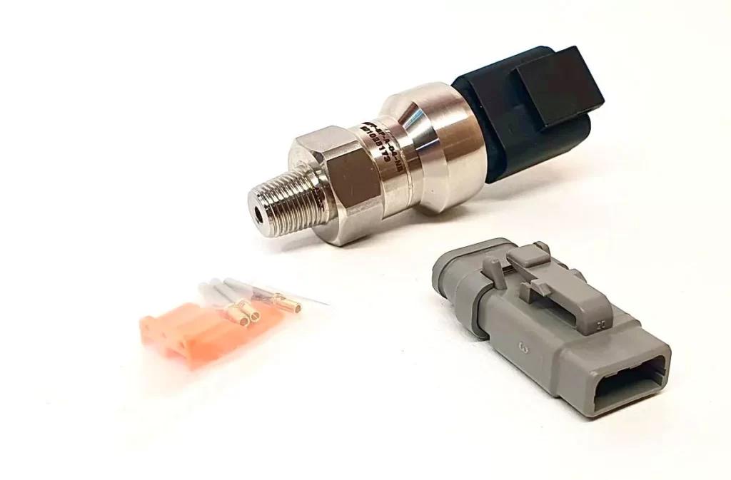
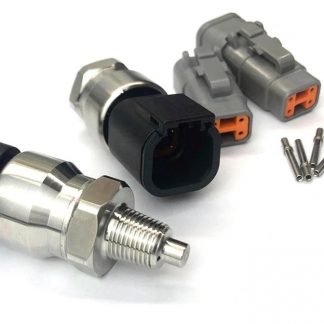
Oil pressure based protection is one of the most common types of engine protection. A sensor is used to monitor oil pressure and the ECU monitors this pressure.

Low oil pressure can result in catastrophic engine failure through spun bearings, damaged camshafts and thrown rods. It can also cause damage to attached components like turbochargers. For this reason, shutting off an engine which has low oil pressure can save vital components.

When racing the risk of oil starvation is increased due to high sustained load while engaged in high g-force cornering, braking, and accelerating. This can cause oil to surge away from the pickup and starve the engine of oil.

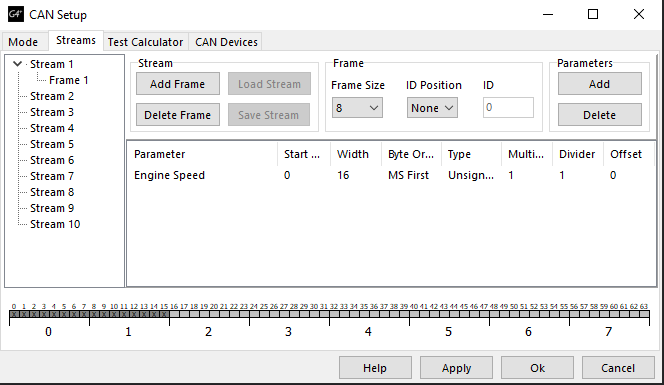
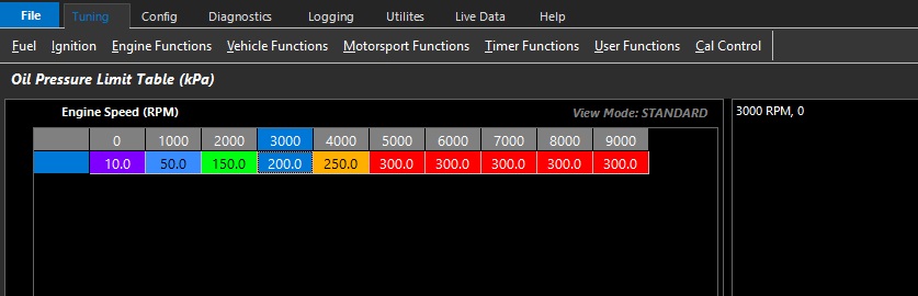
As oil pressure changes with engine rpm and temperature, these factors are often added as tables which change the engine cut activation. The following shows an oil pressure limit table based on rpm and pressure. If the engine is over the set RPM and sees an oil pressure lower than the one in the corresponding cell the limit will kick in, either limiting the engine to a low RPM or shutting off the engine entirely depending on how the limit has been set up.
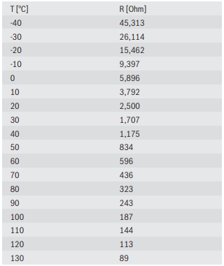
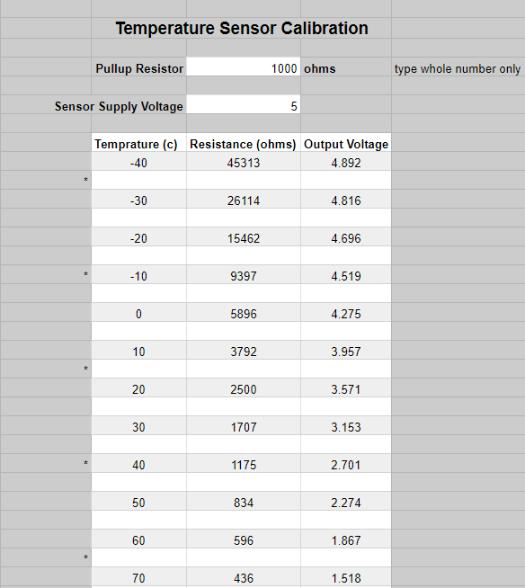
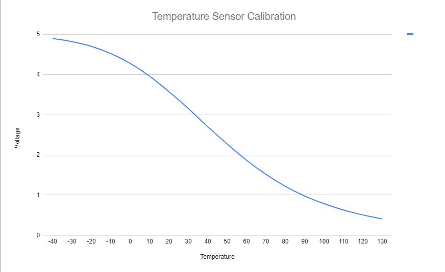
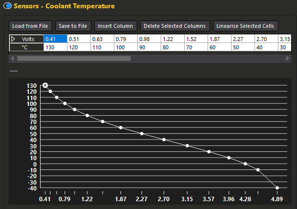
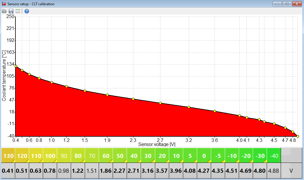
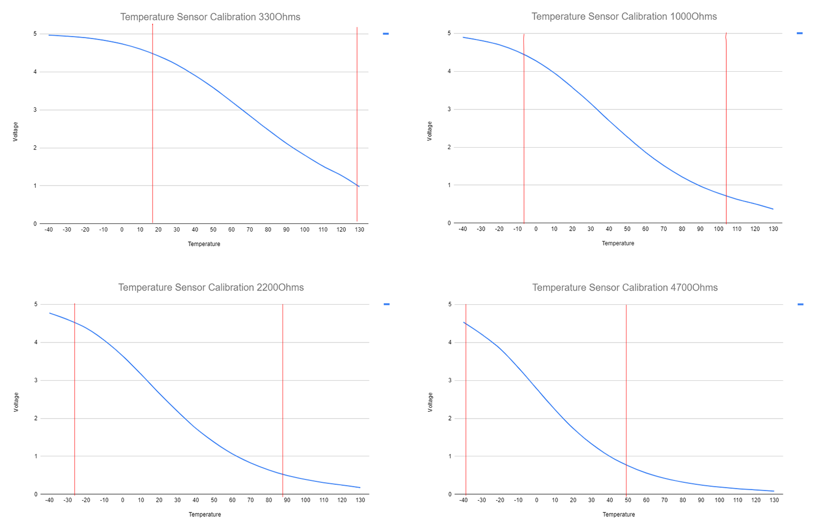
Engine Temperature

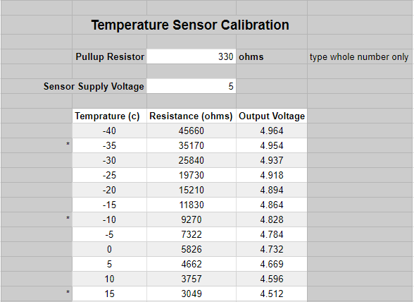
Engine temperature can be based off either coolant or oil temperature, and both are important to keep an eye on.

Oil temperature being too high will usually cause pressure problems before there are issues with the lubrication properties.

Coolant temperature is more commonly monitored, and is included in a basic form in most OEM cars. A high coolant temperature can cause blown head gaskets, warped and softened cylinder heads, and even seized pistons. Even at a lower level, a coolant temperature which is too high can lead to detonation.

For these reasons having engine temperature sensors which allow the ECU to limit RPM, or cut the engine if temperatures get too high can be the difference between an engine which will live to race another day, or an expensive lawn ornament.

Coolant Pressure

Coolant pressure is often related to coolant temperature, but it can also give an insight into other parts of the engine. . A coolant hose which has popped off will cause a drop in coolant system pressure, this can allow the driver to stop and fix the problem before the car overheats. Coolant pressure that is high can be a sign of high engine temperatures which make it more likely for a head gasket to blow due to warping of the mating surface. Irregular spikes in coolant pressures can also be a way to diagnose a blown head gasket as the escaping combustion gases raise the pressure in the coolant system. With the increasing prevalence of combined pressure and temperature sensors adding a coolant pressure sensor and corresponding cutoffs in the ECU is an easy way to monitor leaks within the coolant system.
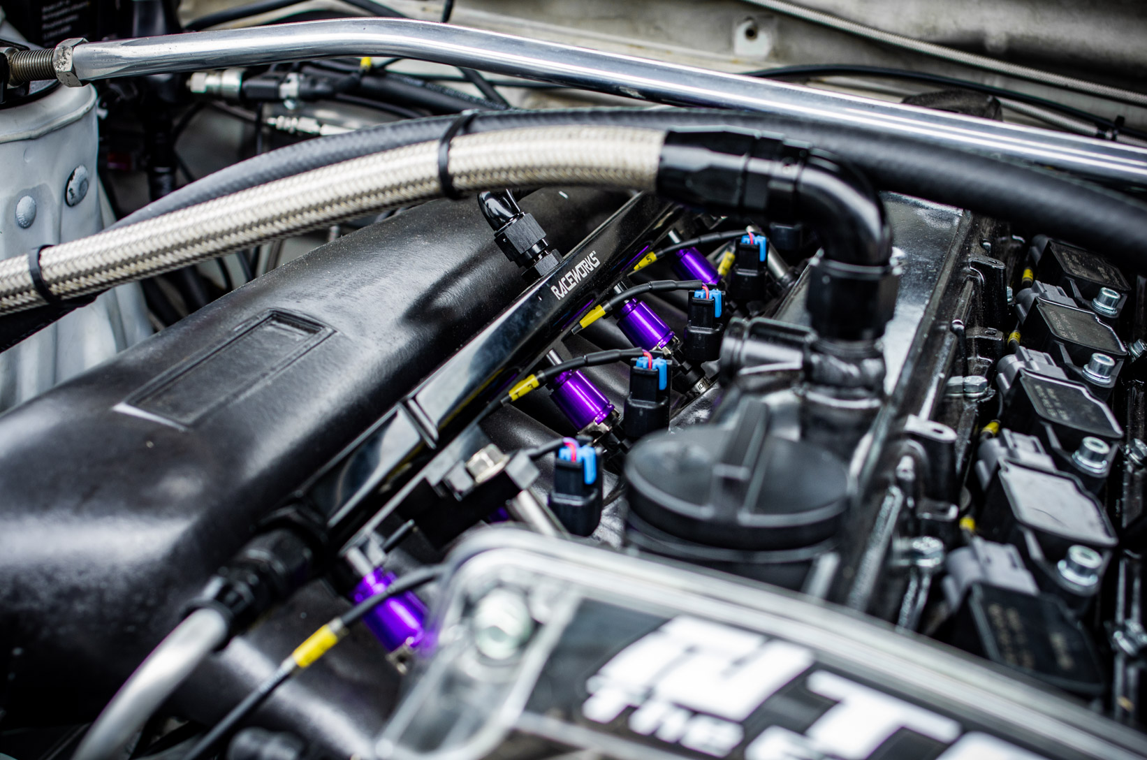
Fuel Pressure

Fuel pressure is another important factor as a drop in fuel pressure will usually lead to less fuel entering the cylinder than expected. This will cause the engine to be lean, which can cause damage. At lower RPM an engine running lean can just result in stalling, and poor performance, but under higher loads it can lead to detonation which may cause engine damage. Running lean will also cause higher cylinder temperatures which can also contribute to engine damage.

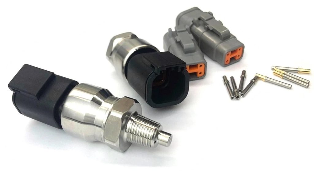
Fuel pressure can drop due to a failed fuel pump, or fuel pressure regulator. If this happens while the engine is under hard acceleration it can cause catastrophic engine failure. Fuel pressure isn’t always monitored as the base pressure is often set with a gauge, but most fuel pressure regulators have a bung which can be used for a sensor which can then be wired into the ECU.
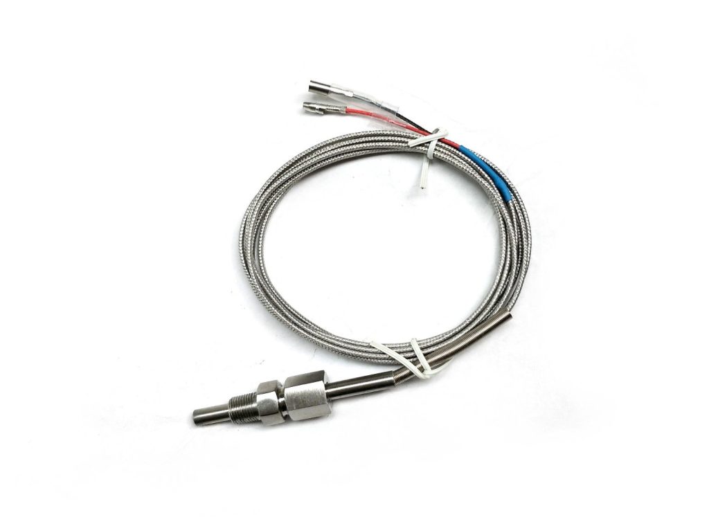
EGT

High Exhaust Gas Temperatures (EGT) can cause damage to engine components, turbochargers, and the engine itself. In a diesel engine high EGTs are generally caused by the engine running too rich and is burning too much fuel compared to the amount of air it is getting.

Generally an EGT safety limiter is in place for diesel engines. The location of the EGT sensor(s) is important in ensuring your limiter numbers are set correctly.

Injector Duty Cycle

Injector duty cycle follows the same logic as fuel pressure with the same problems and dangers. If the injector duty cycle is at 100% then the injectors are effectively wide open. If the injectors are at 100% flow, the maximum amount of fuel is flowing through the injectors, it is then possible for more fuel to be necessary for combustion, but not enough is able to be provided. This will lead to a lean condition, and may cause engine damage. As the injectors are directly driven by the ECU it is usually fairly simple to add a form of injector duty cycle based protection to your ECU.
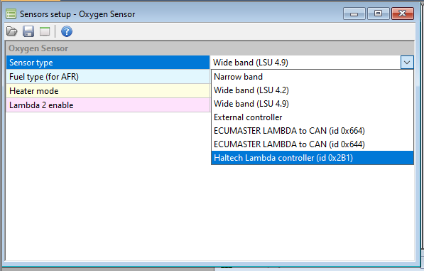
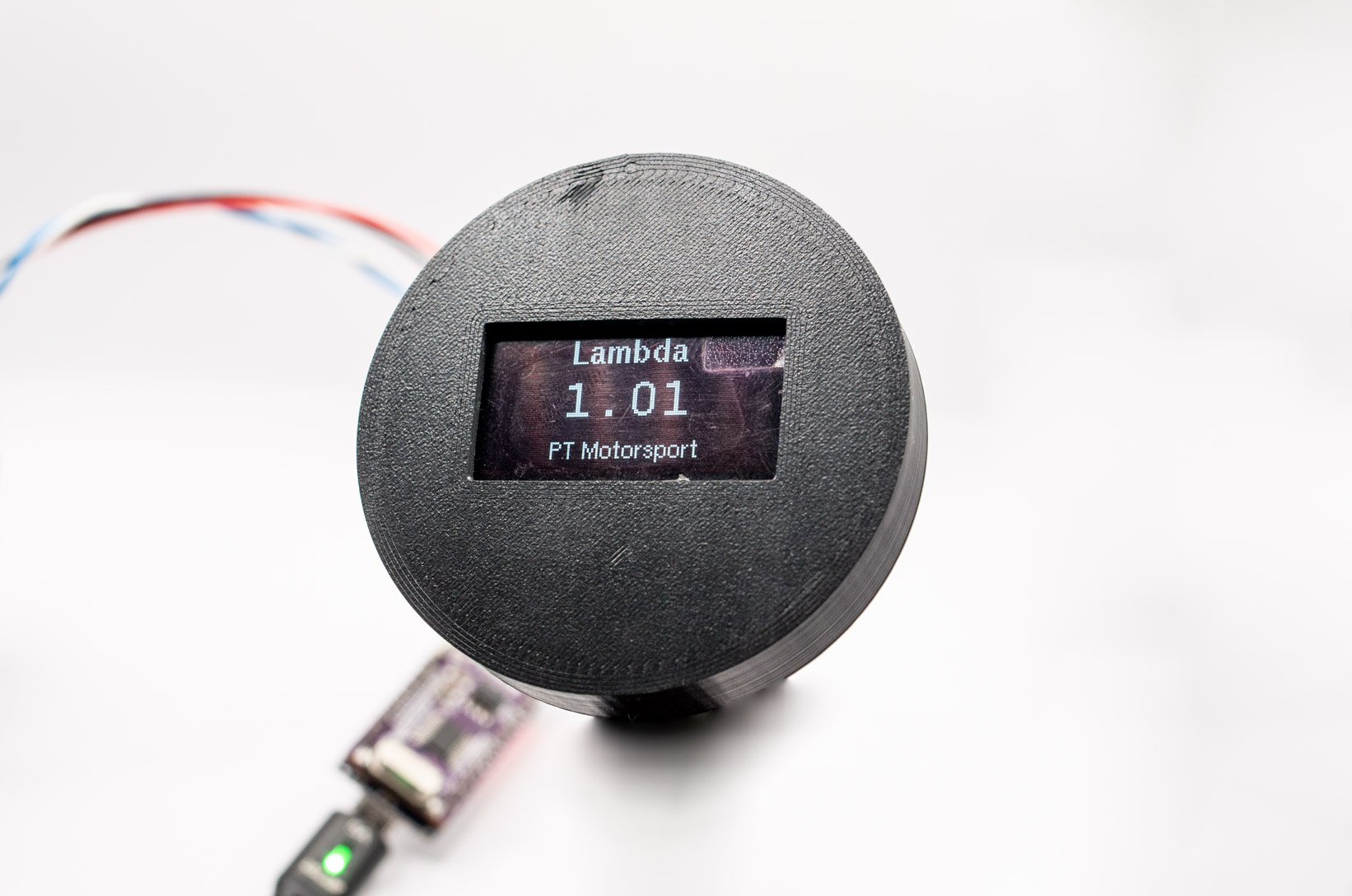
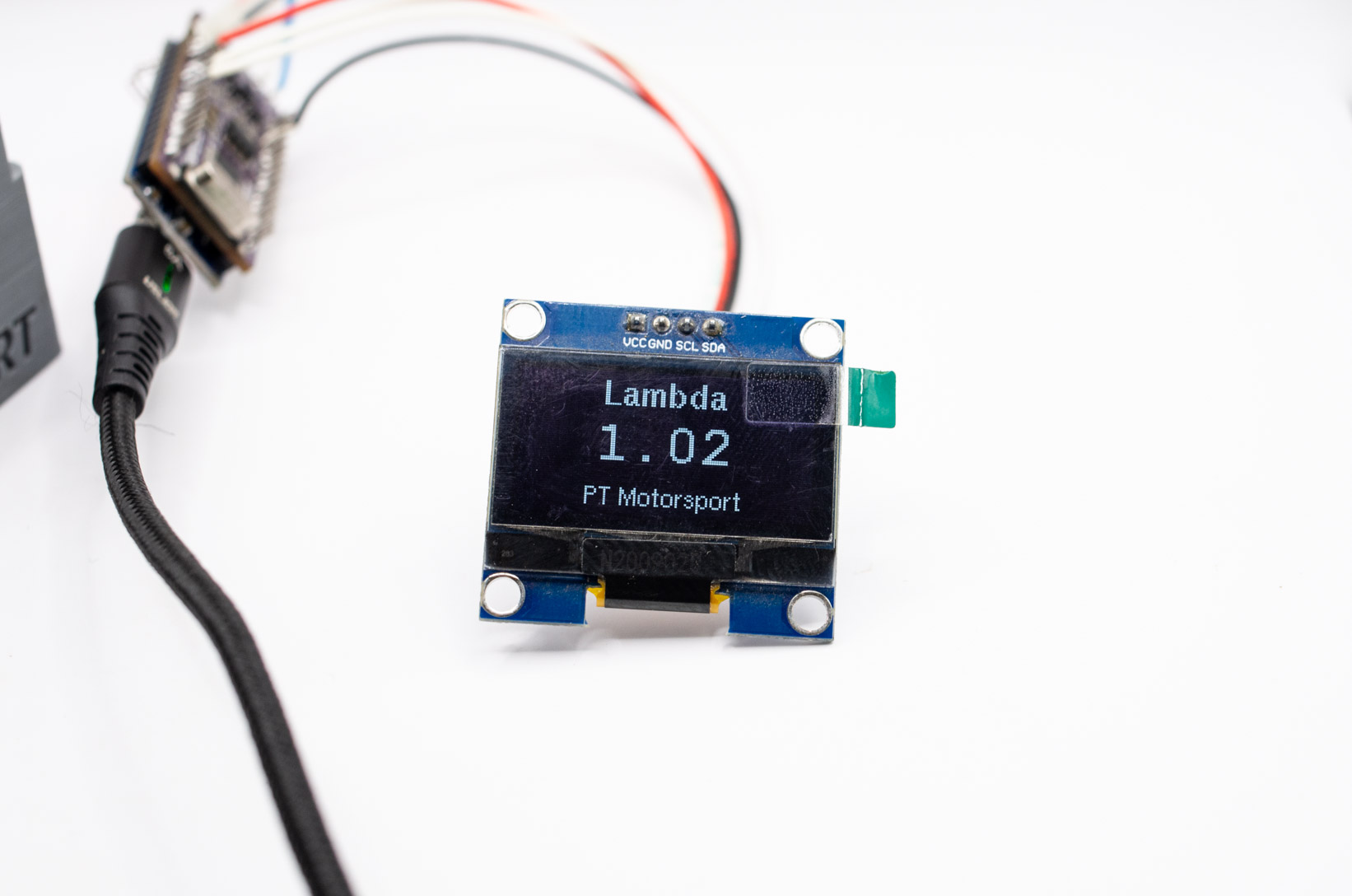
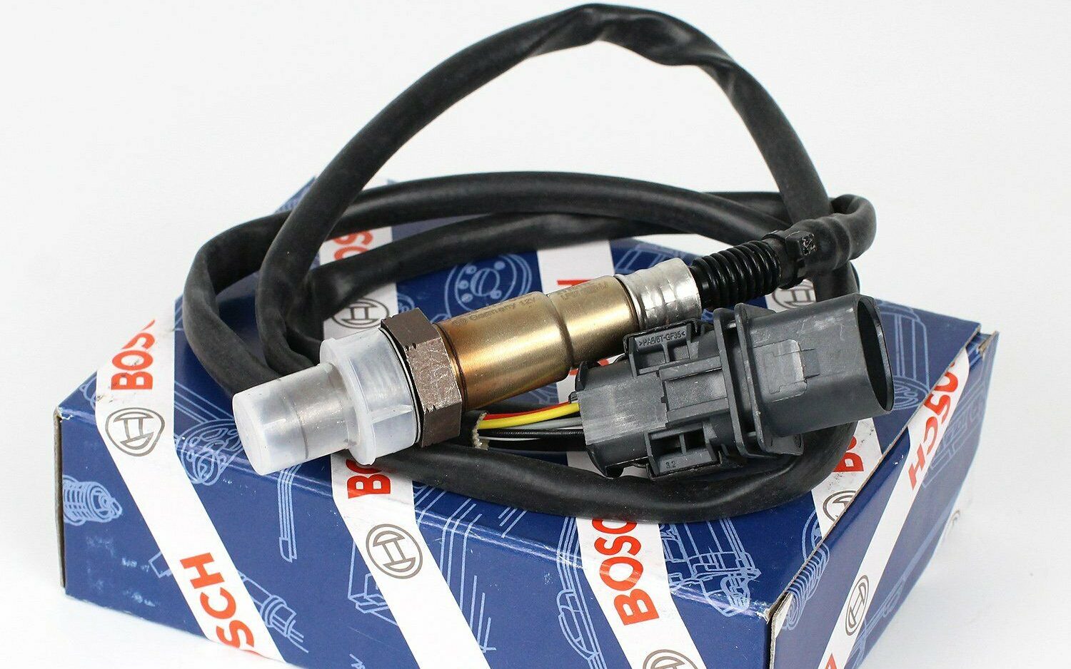
Lambda

Lambda (or AFR) protections also look at fueling, and can be another method to protect an engine from damage due to running lean, but Lambda protections can also be used to protect an engine from running too rich. As mentioned above, an engine which is running too rich can have EGTs which are too high. Using Lamdba based protections allows for a large scope of protection and can be used to prevent other issues. However, due to wideband sensors being positioned in the exhaust it is inherently a reactive system and while it will catch problems it may be too slow to effectively protect the engine from things like a sudden drop in fuel pressure. With that being said, as Lambda is generally monitored anyway it is not a particularly large extra step to set up when configuring your ECU.

Boost/MAP

While a properly tuned car is unlikely to overboost, especially to a level that causes engine or component damage, it is still possible for mechanical failures to occur. For example, a wastegate solenoid line can break, causing the turbo to continue building boost beyond where the wastegate should have opened. This can lead to increased cylinder pressures, causing bent rods, broken pistons, and lifted heads. For this reason a separate boost based engine limiter can be set up to limit the engine’s RPM if boost exceeds the set amount.
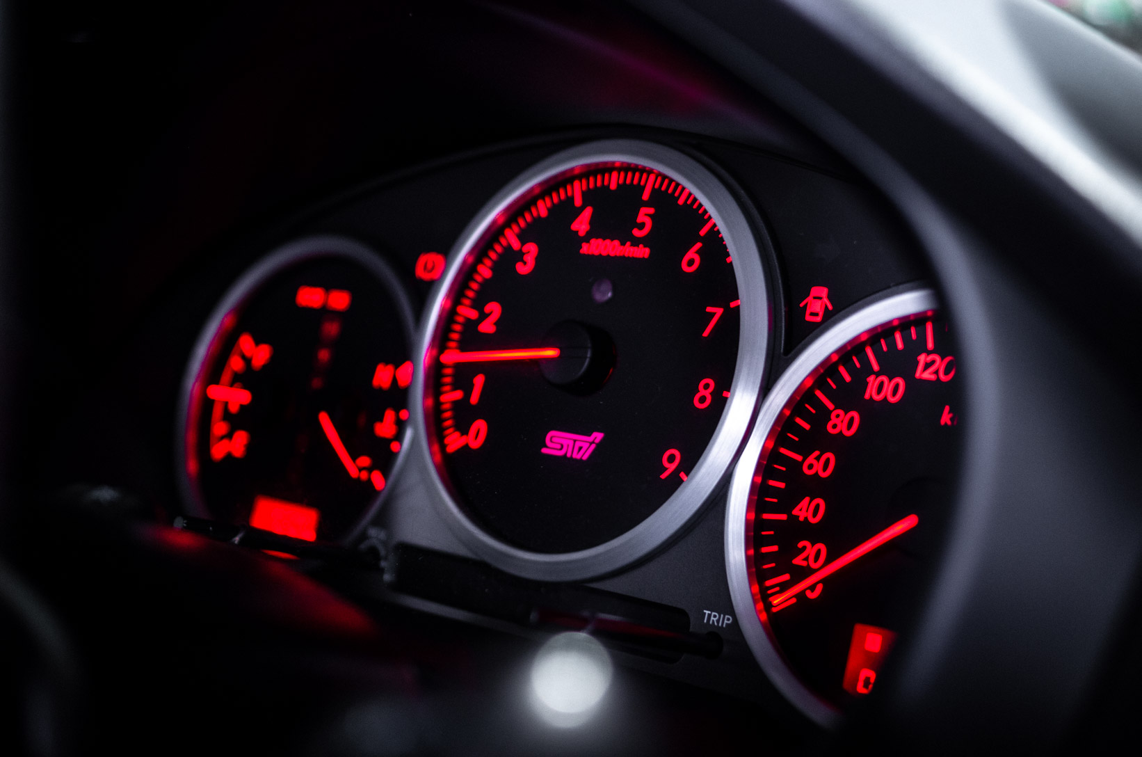
RPM

A general RPM limit is a great idea, as while an engine revving to the moon will sound incredible, it will likely only do that once before it starts to make some less incredible sounds. There is no hard and fast rule about what your RPM limit should be, but your tuner or engine builder should have a good idea of where to set the limit.

It is possible to have engine protection which is set up in an incorrect fashion. An ignition cut at high RPM can cause valve float due to high exhaust pressure from unburned fuel igniting in the exhaust manifold, on cars with shim-over-bucket style cam followers this can cause the shim to come out of its seat and cause engine damage. It is also important that the limits are set correctly. The location of a sensor can effect the figures which are read by the ECU. Or the numbers in the ECU might not be appropriate.

While not every aftermarket ECU will have the option to turn on all of these protections from a single tuning panel, many are able to be added through the use of User Defined tables. Engine protections also aren’t a magic bullet, and failures can still occur, but having as many safeties as feasibly possible will help ensure that smaller failures don’t turn into major ones. It is always important to talk to your wiring harness manufacturer, tuner, and engine builder about which forms of engine protection are best for you, and how best to implement them.

  • Product on sale
    CANbus IO Expander - Nano
    CANbus IO Expander – Nano
    $49.00
  • Syltech - Combined Pressure and Temp Sensor
    Syltech – Combined Pressure and Temp Sensor
    $165.00
  • Tesa Tape - 51036 - Wiring Harness Tape
    Tesa Tape – 51036 – Wiring Harness Tape
    $15.00
  • CAN Checked - MFD15 52mm CAN Gauge
    CAN Checked – MFD15 52mm CAN Gauge
    $469.00
  • Open Barrell Splice kit with crimping pliers
    Open Barrel Splice Kit – With Crimping Pliers
    $108.90
  • ECU Master EMU-BLACK
    ECU Master EMU-BLACK
    $1,760.00

Posted on

Understanding G-Codes and M-Codes in 3D Printing with Klipper Firmware

When venturing into the world of 3D printing, a fundamental aspect of controlling your printer is familiarity with G-codes and M-codes. G-codes (geometric codes) and M-codes (miscellaneous codes) are sets of instructions that command the movements, actions, and operations of your 3D printer. In the context of Klipper firmware, mastering these codes becomes particularly valuable for customizing and optimizing your printing experience.

The Power of G-Codes: Navigating the 3D Space

G-codes are the backbone of 3D printing, dictating how the printer’s motors should move to produce a desired object layer by layer. Whether it’s a rapid movement to a new position (G0), a controlled extrusion of filament (G1), or homing all axes (G28), G-codes are the language through which you communicate with your 3D printer. Understanding and utilizing G-codes allows you to control the printer’s movements with precision, enabling the creation of intricate and accurate prints.

Example:

G1 X10 Y20 Z30 F3000

In this example, the printer is instructed to move to the coordinates X=10, Y=20, Z=30 at a feed rate of 3000 mm/min.

Navigating System Operations with M-Codes

Complementing G-codes, M-codes handle miscellaneous functions such as temperature control, bed leveling, and emergency stops. These codes govern crucial aspects of the printing process, ensuring that the printer operates within specified temperature ranges, executes proper homing procedures, and handles emergencies responsibly.

Example:

M104 S200

This M-code sets the extruder temperature to 200 degrees Celsius, ensuring the filament is at the optimal temperature for extrusion.

Why Knowing G-Codes and M-Codes Matters

Understanding G-codes and M-codes empowers 3D printing enthusiasts to optimize their printing workflows. Knowing how to home the printer, control temperatures, and manage extrusion precisely allows for the fine-tuning of prints and troubleshooting of potential issues.

Moreover, delving into these codes opens up possibilities for customization. Whether you’re adjusting the speed of movements, implementing auto bed leveling (G29), or defining specific extrusion rates (G92), G-codes and M-codes provide the flexibility needed to tailor your 3D printing experience to your exact specifications.

As you navigate the world of 3D printing with Klipper firmware, this cheat sheet serves as a handy reference, condensing essential G-codes and M-codes into a single, accessible resource. Mastery of these codes transforms the seemingly complex task of 3D printing into a more manageable and customizable endeavor, allowing you to unleash the full potential of your 3D printer.

3D Printing G-Code Cheat Sheet

Here is a quick one pager we’ve prepared that we keep close to out 3D printing workstation, very helpful for when reading g-code for troubleshooting, or when you’re writing your own macros.

**Movement Commands**
G0 / G1 Rapid / Linear Move
Example: `G1 X10 Y20 Z30 F3000`
G28 Home all axes
Example: `G28`
G92 Set position
Example: `G92 E0` (reset extruder position to 0)
**Temperature Control**
M104 Set extruder temperature
Example: `M104 S200`
M140 Set bed temperature
Example: `M140 S60`
M109 Wait for extruder temperature
Example: `M109 S200`
M190 Wait for bed temperature
Example: `M190 S60`
**Extrusion Control**
M82 / M83 Set extruder to absolute (M82) or relative (M83) mode
Example: `M82`
G92 E Set extruder position (used with absolute mode)
Example: `G92 E10`
G1 E Extrude filament
Example: `G1 E10 F100`
**Positioning Modes**
G90 Set to absolute positioning mode
Example: `G90`
G91 Set to relative positioning mode
Example: `G91`
**Bed Leveling and Mesh**
G29 Auto bed leveling
Example: `G29`
G80 Cancel mesh bed leveling
Example: `G80`
**Fan Control**
M106 Turn on fan
Example: `M106 S255`
M107 Turn off fan
Example: `M107`
**System Commands**
M112 Emergency stop
Example: `M112`
M503 Print settings (configured in firmware)
Example: `M503`
M665 / M666 Delta parameters (if applicable)
Example: `M665 L200.000 R100.000 H400.000 B125.0 X0.000 Y0.000 Z0.000`
Posted on

Autosport and Deutsch Connector Heatshrink Boot Size Charts

Deutsch Autosport connectors are the standard for connectors in the autosport industry with the AS series connectors being used by race winning teams. In order to correctly boot these connectors, the proper boot must be used. Below is a chart of Autosport connectors and their corresponding boots, both straight and 90 degree.

Shell SizeStraight Boot90 Degree Boot
RaychemHellermanRaychemHellerman
ASX (Size 02)203W301-25-G021037-4-G223W6011182-4-G
ASX (Size 03)204W221-25-G031037-4-G224W221-25-G031182-4-G
ASC204W2211030-4-G224W2211181-4-G
ASL204W2211030-4-G224W2211181-4-G
AS Mini202K121152-42-G222K1211152-4-G
08202K121152-42-G222K1211152-4-G
10202K132152-42-G222K1321152-4-G
12202K142154-42-G222K1421154-4-G
14202K142155-42-G222K1421155-4-G
16202K153156-42-G222K1521156-4-G
18202K153156-42-G222K1521156-4-G
20202K163157-43-G222K1631157-4-G
22202K163157-43-G222K1631157-4-G
24202K174157-43-G222K1741157-4-G

Used commonly in the automotive aftermarket, the Deutsch DT series is a versatile connector. If the part number ends with E007 (DTM) or E008 (DT), then the connector has a bootable end for applications where wires need added protection.

Straight Boot90 Degree Boot
DTM PlugsDTM ReceptaclesHeat Shrink SIzeRaychemHellermanRaychemHellerman
DTM06-2S-E007DTM04-2P-E00712mm202D121152-42-G
(401-52880)
222D1211106-4-G
(411-06019)
DTM06-3S-E007DTM04-3P-E00716mm202D121152-42-G
(401-52880)
222D1211106-4-G
(411-06019)
DTM06-4S-E00716mm202D121152-42-G
(401-52880)
222D1211106-4-G
(411-06019)
DTM06-6S-E00716mm202D132152-42-G
(401-52880)
222D1321106-4-G
(411-06019)
DTM06-08SA-E00724mm202D153156-42-G
(401-56880)
222D1521103-4-G
(411-03024)
DTM06-12SA-E00724mm202D163157-43-G
(401-57980)
222D1631101-4-G
(411-01020)
Straight Boot90 Degree Boot
DT PlugsDT ReceptaclesHeat Shrink SizeRaychemHellermanRaychemHellerman
DT06-2S-E008DT04-2P-E00816mm202D121152-42-G
(401-52880)
222D1211106-4-G
(411-06019)
DT06-3S-E008DT04-3P-E00816mm202D132153-42-G
(401-53880)
222D1321107-4-G
(411-07020)
DT06-4S-E008DT04-4P-E00824mm202D121152-42-G
(401-52880)
222D1211106-4-G
(411-06019)
DT06-6S-E008DT04-6P-E00824mm202D132154-42-G
(401-54880)
222D1321104-4-G
(411-04032)
DT06-08SA-E008DT04-08PA-E00840mm202D153157-43-G
(401-57980)
222D1521101-4-G
(411-01020)
DT06-12SA-E008DT04-12PA-E00840mm202D163157-43-G
(401-57980)
222D1631101-4-G
(411-01020)
Posted on

How to Convert Sensor Calibration Tables

When adding sensors, or configuring an ECU you will often need to input calibration data so that the ECU knows which input values represent what data.

Often calibration tables will be available in ohms like this example from a Bosch Motorsport coolant temperature sensor

For some ECUs this is fine as you can select between units when inputting a calibration table

If this isn’t an option you can manually calculate the voltage using ohms law

V = IR

Unfortunately this takes a lot of time to do manually, and if using a pullup resistor adds more complexity.

Fortunately, with a little bit of spread-sheeting know-how you can create an automatic voltage calculator with the ability to change the sensor input voltage and pullup resistor value on the fly. The below link is to the PT Motorsport sensor calibration converter.

PT Motorsport Sensor Calibration Converter

We have included conversion tables for some common sensors, as well as the pull-up resistor values used by some common aftermarket ECUs.

If you need to convert your own sensor calibration you will need to first download the document so that you can edit it.

The main section of interest is the grey table. This has the sections for altering the pullup resistor and sensor supply voltage values as well as the sensor calibration data.

For the pullup resistor value you can either input the value you intend to use, or if you are using an ECUs internal pullup resistor you can input the value. The table includes some of the common ECU pullup resistor values. If you are unsure which pullup resistor to use, or want to know more about why we use them, read this article.

You can also enter the sensor supply voltage. In most automotive applications this will be 5V.

Finally, enter the sensor calibration data.

Using the example Bosch sensor above and using it with the internal pullup resistor in a Haltech ECU we can input the following data. Where there isn’t enough data to fully complete the table you can simply remove those rows.

As the data is entered the table will update, giving the correct output voltage values. Along with the table, a graph is also generated. This graph is useful to determine whether your pullup resistor is suitable for your application. For more information on why we use a pullup resistor, and how to choose the correct one for your application see our article.

With this data we can input the values into our ECU calibration table

This will look different across ECUs, the below is from the ECU Master EMU Black software, but using the same values (for this example that would mean wiring in a 1000ohm resistor rather than using the internal 2200ohm)

Posted on

What is a pullup resistor and which one do I need?

You may have seen references in articles to pullup resistors, or seen their use in wiring documentation. A pullup resistor diagram will generally look like this:

But what is a pullup resistor, and why do we even need one?

A pullup resistor is a regular resistor which we use to provide a known resistance. Why do we need a known resistance though?

The simple answer is that ECUs aren’t multimeters and generally can’t directly measure resistance. Instead using voltage inputs for receiving information. In a sensor with only two wires, there is no voltage being introduced and therefore no voltage for the ECU to measure. To provide a voltage we use a resistor from the ECUs 5V output to the signal wire of the sensor.

This gives the ECU a variable voltage output from our sensor. This also means that we need a pullup resistor for every input.

For ensure the correct variable voltage we need a resistor before and after the ECU sensor voltage input. Our pullup resistor is the resistor that’s before the input, and our sensor acts as the resistor after the input.

To show why a resistor is needed on each side, lets take a look at what our circuit looks like without each resistor.

Without the pullup resistor, the 5V output would travel directly to the ECU input, giving a signal of 5V all the time, regardless of what the sensor is doing.

Without the sensor the ECU would simply see 0V all the time.

What about pullup resistors for switches?

You may also see pullup resistors used in switch diagrams or referenced in ECU guides.

Why do we need a pullup resistor for a switch when it should just be on or off?

Once again, we will look at what happens without the resistor.

In this case when the switch is closed we end up with a short directly from the 5V output to ground.

With the resistor in place, the ECU will see 5V when the switch is open, and 0V (Ground) when the switch is closed.

How Do I know what resistance I need?

Generally for switched applications a 1kohm resistor is appropriate, but for sensor inputs it can be slightly more complicated.

If you use the PT Motorsport Sensor Calibration Converter (full instructions here) you will end up with a graph of the values across the voltage range. If you change the pullup resistor value you will notice that the scaling of the graph changes.

In this instance, as the resistance increases the resolution at various points changes. We want our most used ranges of data to be on the sloped part of the graph. As shown below, the different resistor values lead top different “ideal” ranges.

Depending on your application, you would select a resistor that gives good resolution in the area you expect to see.

For example, for a pre-turbo IAT sensor a 2200ohm resistor would be appropriate as a temperature range of -20 to 80 degrees is within our expected range.

For an oil temperature sensor, a 330ohm resistor would be appropriate as the higher resolutions are in the higher temperature range.

Where should I install my pullup resistor?

If your ECU doesn’t have an internal pullup resistor, or if it isn’t an appropriate resistance, where should you install your own pullup resistor?

Depending on the type of sensor and the available connectors you can either add your pullup resistor in-line in the harness or at the sensor connector. If you are running a 2 wire sensor having the pullup resistor near the ECU makes sense as you can add the resistor before you branch your wiring harness meaning that less wire needs to be run. That being said, a pullup resistor can be located anywhere practical using the method outlined below.

To wire a pullup resistor like this we use open barrel splices. Simply strip a short section of wire from your 5V signal wire and your sensor wire, and crimp the resistor across the wires. Our example is un-covered, but in your own harness this would then be covered by 4mm ATUM heat-shrink.

If you are running a Syltech Combined Pressure and Temperature sensor then you can use a bootable Deutsch connector to protect and hide the resistor at the sensor connector end of the loom. In this application having the pullup resistor at the sensor end works as the sensor needs to have a 5V power wire to drive the pressure sensor, so there are no additional wires run.

In this application, insert the wire into the Deutsch pin, then insert the resistor leg before performing your crimp.

Once crimped, insert the pins into the correct locations. The wires joined by the resistor will need to be inserted at the same time. The end of the bootable Deutsch connector can then be covered with heat-shrink or an appropriate boot.

Posted on

Time Attack Tas 2022 – Using Technology to get a new PB!

Time Attack Tas (TaT) is an event we very much look forward to every year, competing in every event since its inception.

This year was another great event organised by the Hobart Sporting Car Club at Baskerville. We’re very grateful for their continued dedication to the sport and this event.

Peter competed in his R33 Skyline GTST and took 2nd place in Club Class. Peter negotiated his usual struggle for traction and drove his way to a new PB of 59.1 seconds. 

Peter often drives with a heavy foot which is the cause of the majority of his traction issues. We were able to assist slightly in the part throttle area of driving by changing the mapping of the drive by wire throttle.

Another reason we love drive by wire.

You can see here in the NSP software, the vertical axis is the actual percentage of throttle opening vs the horizontal axis which is the accelerator pedal position. The dashed line represents a linear relationship, which is close to where we started, and the solid line is where we finished for the day, giving the driver much more part throttle “resolution”. This significantly improved part throttle drivability and made it easier to get out of corners cleanly, contributing to the new PB.

NSP makes this very easy to map with the spline handles you can use to drag the curve around. This feature isn’t unique to Haltech though, with most ECU manufactures offering this feature too.

Our beloved EVO piloting tuner, Ash, was also competing and was able to secure 3rd place with a 59.6 lap time, unfortunately unable to drive his vehicle home though, that story for another time…


  • 4 Port CAN Hub
    4 Port CAN Hub
  • Open Barrell Splice Kit
    Open Barrel Splice Kit – 100pcs
  • ECU Master EMU-BLACK
    ECU Master EMU-BLACK
  • Subaru GC8 APP Bracket
    Subaru GC8 APP Bracket