
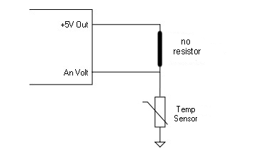
You may have seen references in articles to pullup resistors, or seen their use in wiring documentation. A pullup resistor diagram will generally look like this:

But what is a pullup resistor, and why do we even need one?
A pullup resistor is a regular resistor which we use to provide a known resistance. Why do we need a known resistance though?
The simple answer is that ECUs aren’t multimeters and generally can’t directly measure resistance. Instead using voltage inputs for receiving information. In a sensor with only two wires, there is no voltage being introduced and therefore no voltage for the ECU to measure. To provide a voltage we use a resistor from the ECUs 5V output to the signal wire of the sensor.
This gives the ECU a variable voltage output from our sensor. This also means that we need a pullup resistor for every input.
For ensure the correct variable voltage we need a resistor before and after the ECU sensor voltage input. Our pullup resistor is the resistor that’s before the input, and our sensor acts as the resistor after the input.
To show why a resistor is needed on each side, lets take a look at what our circuit looks like without each resistor.
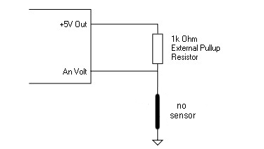
Without the pullup resistor, the 5V output would travel directly to the ECU input, giving a signal of 5V all the time, regardless of what the sensor is doing.
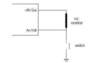
Without the sensor the ECU would simply see 0V all the time.
What about pullup resistors for switches?
You may also see pullup resistors used in switch diagrams or referenced in ECU guides.
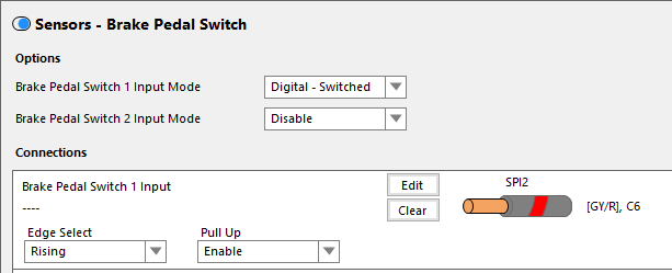
Why do we need a pullup resistor for a switch when it should just be on or off?
Once again, we will look at what happens without the resistor.
In this case when the switch is closed we end up with a short directly from the 5V output to ground.
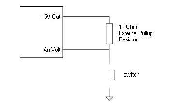
With the resistor in place, the ECU will see 5V when the switch is open, and 0V (Ground) when the switch is closed.
How Do I know what resistance I need?
Generally for switched applications a 1kohm resistor is appropriate, but for sensor inputs it can be slightly more complicated.
If you use the PT Motorsport Sensor Calibration Converter (full instructions here) you will end up with a graph of the values across the voltage range. If you change the pullup resistor value you will notice that the scaling of the graph changes.
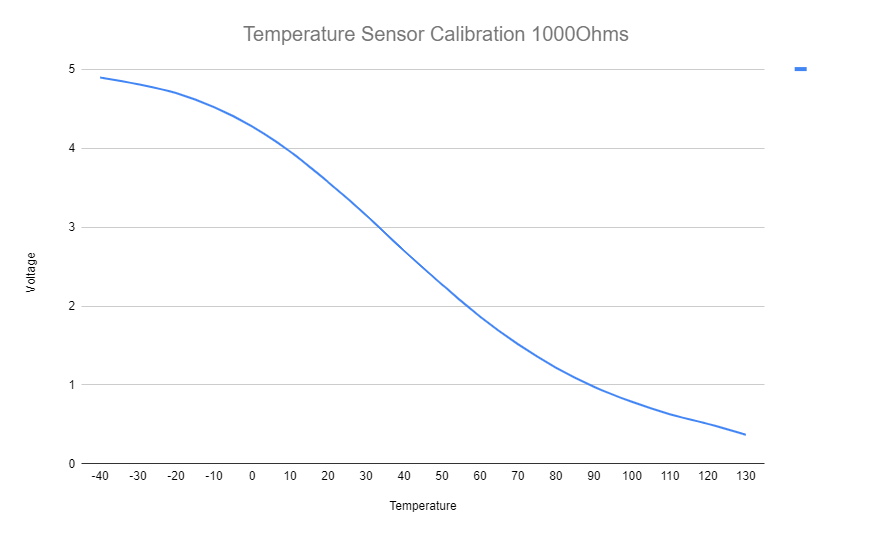

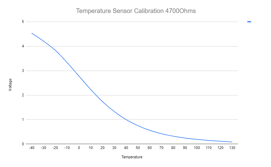
In this instance, as the resistance increases the resolution at various points changes. We want our most used ranges of data to be on the sloped part of the graph. As shown below, the different resistor values lead top different “ideal” ranges.
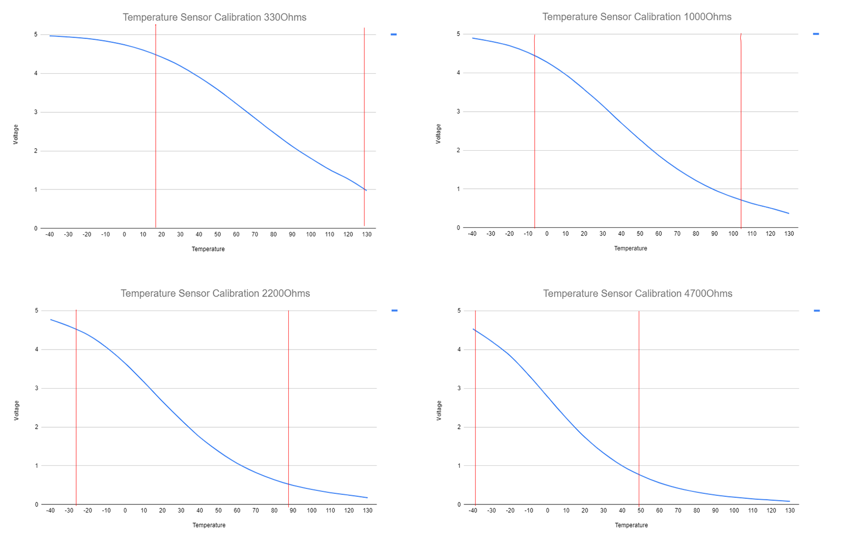
Depending on your application, you would select a resistor that gives good resolution in the area you expect to see.
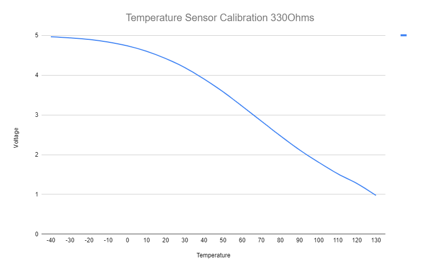
For example, for a pre-turbo IAT sensor a 2200ohm resistor would be appropriate as a temperature range of -20 to 80 degrees is within our expected range.
For an oil temperature sensor, a 330ohm resistor would be appropriate as the higher resolutions are in the higher temperature range.
Where should I install my pullup resistor?
If your ECU doesn’t have an internal pullup resistor, or if it isn’t an appropriate resistance, where should you install your own pullup resistor?
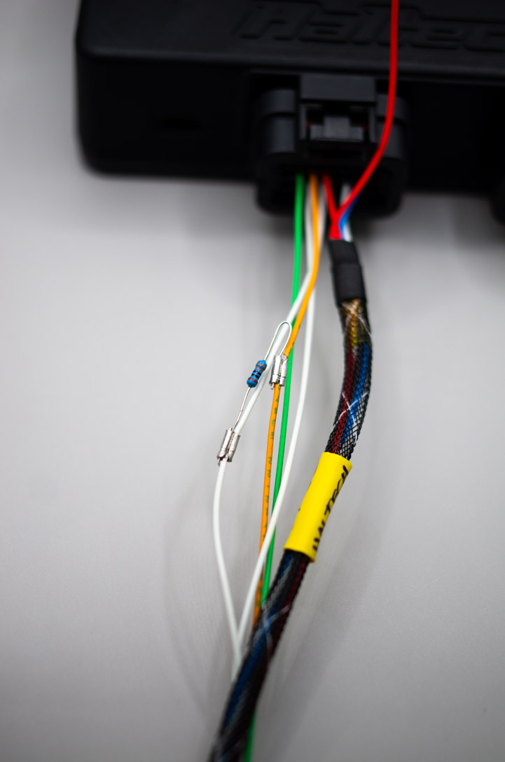
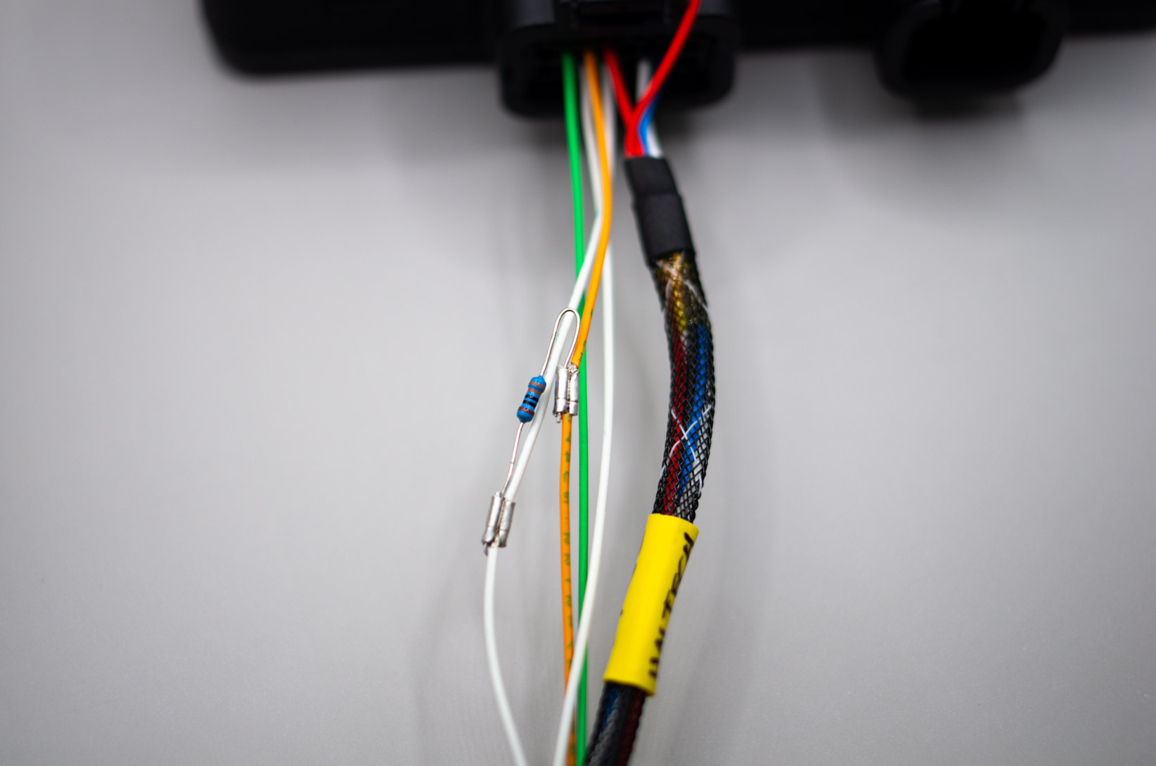
Depending on the type of sensor and the available connectors you can either add your pullup resistor in-line in the harness or at the sensor connector. If you are running a 2 wire sensor having the pullup resistor near the ECU makes sense as you can add the resistor before you branch your wiring harness meaning that less wire needs to be run. That being said, a pullup resistor can be located anywhere practical using the method outlined below.
To wire a pullup resistor like this we use open barrel splices. Simply strip a short section of wire from your 5V signal wire and your sensor wire, and crimp the resistor across the wires. Our example is un-covered, but in your own harness this would then be covered by 4mm ATUM heat-shrink.
If you are running a Syltech Combined Pressure and Temperature sensor then you can use a bootable Deutsch connector to protect and hide the resistor at the sensor connector end of the loom. In this application having the pullup resistor at the sensor end works as the sensor needs to have a 5V power wire to drive the pressure sensor, so there are no additional wires run.
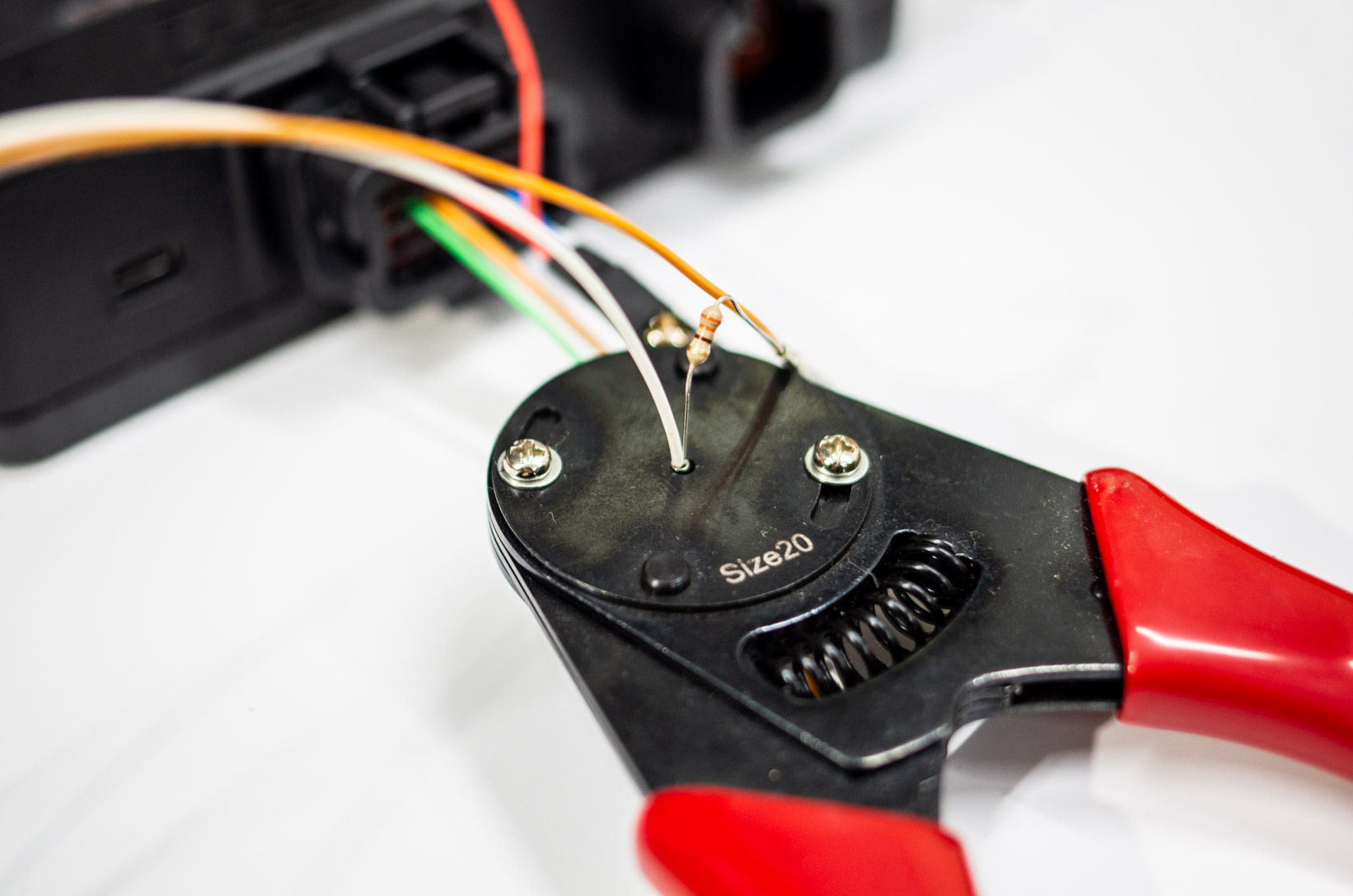
In this application, insert the wire into the Deutsch pin, then insert the resistor leg before performing your crimp.
Once crimped, insert the pins into the correct locations. The wires joined by the resistor will need to be inserted at the same time. The end of the bootable Deutsch connector can then be covered with heat-shrink or an appropriate boot.